

The common resistor or fixed resistor is a component made from some conducting material the size, shape, and conductivity of which are arranged to determine the amount of electrical resistance needed. The amount of resistance is measured in ohm (Ω).
Inside electronic equipment are resistors of many types and sizes with resistance values ranging from less than 1 ohm to many million Ω.
The resistors are classified into fixed or variable resistors. Let’s look at fixed resistors, also called resistors.
Resistors are found in many sizes and shapes according to the amount of resistance they present, some special performance feature they must have, and the amount of heat generated when working.
Symbols and Types
Figure 1 shows the symbols used to represent a resistor and the types of resistors commonly found in electronic circuits.

The symbol shown in (a) was adopted by the American system of symbols. In European equipment the schematics or circuit drawings represent the resistor as shown in (b).
The most commonly used resistors are carbon composition and carbon film types, as shown in Figure 1(c) where the resistive element is a thin layer of carbon strips deposited onto a ceramic rod.
Another type is the metal film resistor or film resistor, with the same external aspect as the carbon type. In this type, metal is evaporated onto ceramic rods forming a thin film.
These resistors are cheap and can be easily fabricated in a large range of values. They are intended for applications in low-power or small-current circuits. The disadvantage of carbon resistors is that they are noisy.
When desiring resistors that can operate with large currents, the wirewound type shown in Figure 1(d) is preferred.
Those resistors are formed by turns of metal wires (alloys such as nickel, chromium, iron, siver, etc.) onto a ceramic rod. The material, gauge, and number of turns determine the amount of resistance, the size, and how much heat they can handle.
Specifications
When replacing ortesting any electronic device it is necessary to know its specifications. The main specifications for resistors are:
A. Value
The value is the amount of resistance in Ω (?) of a resistor. In large-size types the resistance can be found on the body of the device, the same as in the wirewound resistors (See Figure 2).

But, in smaller types such as carbon and metal film types as well as SMDs, there isn’t enough space to display the resistance value. In this case, and also to make the manufacturing process a bit easier, a color code is used.
Color bands or stripes are printed on the resistor body. Accordingly, the position in the equipment is part of the meaning of a band.
Combining the two, the resistance value of any resistor can be found. In addition to the value in Ω, the color bands also indicate the tolerance of the component.
Table above indicates how the value and tolerance of a resistor is read using the color code.
Notes on Table:
1. If the resistor is a three-band type, the tolerance can be assumed as 20%
2. If the resistor is a three- or four-band type the temperature coefficient is not indicated.
Example- A resistor has colored bands in this sequence: red, violet, orange, and silver. (Read the colored bands from the end to the center.)
Bands 1 and 2 form the number 27. Band 3 indicates that we must multiply this value by 1,000. The resistance is 27,000 Ω. Band 4 indicates that the tolerance is 10%.
B. Dissipation
The size and the material the resistor is made of determine how much heat it can produce without burning. Based on the application the resistors are to be used for, resistors must be chosen in different sizes or dissipation capacities.
The dissipation or power rate of a resistor is specified in watts (W). Small resistors (metal film or carbon) have dissipation in the range between 1/8 and 2 W.
Wirewound types can be found in dissipation starting from 1 or 2 W to more than 200 W. Figure 3 shows the differences in size between carbon resistors according to their dissipation.

From the smaller to the greater the dissipations are 1/8, 1A, and 1/2 W.
C. Tolerance
It is impossible to manufacture a resistor with an exact value of resistance. This is not necessary as the electronic circuits are designed to operate within a certain band of value of components and voltages.
The difference between the value specified for a component and the real value or measured value is called tolerance.
Resistors can be found in tolerance ranges from 1 percent to 20 percent. This means that a resistor indicated as 1000 Ω/10 percent unit can really present resistances between 900 and 1100 Ω.
As a consequence, it is not necessary make resistance with all values between 900 and 1,100 Ω, as the 1000 Ω-resistor covers that range. So, the reader will be surprised when observing that the resistors are found in few common values, according to their tolerances.
The basic values are determined by a commercial series of values.
Table bellow shows that resistors of 47 Ω, 470 Ω, 4700 Ω, 47,000, 470,000 x 20 percent and many other values in multiples of 10 can be found, but not 39 Ω, 390, or 3,900 Ω.
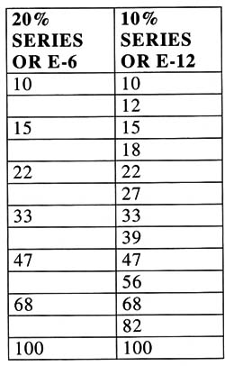
These values are found only in 10 percent resistors. In the same manner, you’ll never find a 3.4 Ω, 34 Tab/e14 Ω, 340 Ω, etc., resistor with 10 or 20 percent tolerance because it doesn’t exist.
Where Resistors are Used
The resistors are the most common of the electronic components.
They are used in all applications where a current must be limited or a voltage steps down.
In electronic circuits the main application for resistors is in bias or stepping down a voltage. Many elements of a circuit must operate with voltages lower than supplied by the power supply.
This means that resistors must be used to step down the voltage to the desired value. These resistors are called bias resistors.
Testing
When heated by excess current, the resistors can open or burn. Although a dark area in the body of the component is an evident sign that it is damaged, in some cases the component doesn’t present any other visible signs of problems.
Resistors are tested using the multimeter (VOM). Desolder one terminal of the component and take it off of the printed circuit board or out of the circuit and measure the resistance.
Don’t measure it while still in the circuit because the multimeter can indicate R the resistance of the circuit, not that of the component.
Figure 5 shows how to do this test.

Remember to consider the tolerance when reading the value displayed by the multimeter and comparing it with the value displayed by the component.
When replacing a resistor use a unit of the same type and same value. The dissipation, in some cases, can be higher if enough space is available for its placement.


