The structure and the operation principle of a power MOSFET are the same as the common MOSFET. The differences are in the size and shape of the silicon chip used when the device is manufactured. (See more in ART107E)
Several technologies are used to produce these devices giving to the POWER-FET transistor names such as VFETs, power FETs, DFETs, and TMOS. The power FETs operate the same way the common MOSFET operates.
A voltage applied to the gate can control the amount of current flowing across the device.
High-current devices such as solenoids, motors, electromagnets, relays, heaters, and lamps can be controlled by power FETs in the same kind of stages as the ones that use power bipolar transistors or Darlington transistors.
The main advantage found in the use of power FETs is the low resistance presented when conducting a current (called Rds or drain source resistance). Because the amount of heat produced by the device depends on this resistance, power FETs can control much larger currents than the equivalent bipolar transistor while generating less heat.
Symbol
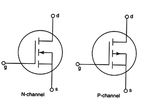
Figure 1 shows that the power FETs can be found in two types - N and P channel.

They look the same as a power bipolar transistor because they use the same bodies.
As with any other power transistor, the N-channel P-channel power FETs must be mounted in heat sinks to transfer to the all the heat they generate when working.
Specifications
The power FETs are identified by a part number. A popular series of power MOSFETs and produced by many manufacturers including International Rectifier, Fairchild, and Motorola is the lRF series.
All devices of this series have part designations beginning with IRF: lRF640, IR720, lRF630, lRF730, etc.
By knowing the name (part number), it is possible to find the electrical characteristics of a Power FET in handbooks or on data sheets. The principal characteristics are as follows.
A. Maximum voltage between drain and source-the maximum voltage that can be applied to the device without burning it. Common types have voltages ranging from 50 to 1000 volts. This specification can be indicated as Vds (max).
B. Maximum drain current-the highest current that can be controlled by the device and can range from 1 to 50 amperes. This specification is abbreviated by Id or ld (max).
C. Dissipation power-the amount of heat that the device can transfer to the surrounding area. It is measured in watts and can range from 10 to 250 watts.
D. Resistance between drain and source in the on state-the most important of the power FET’s specifications. The amount of heat generated by the device depends on this resistance as it operates in more of the applications as an electronic switch. The product of this resistance multiplied by the square of the current gives the generated power. It is easy to see that the lower this resistance, the more efficient the device is when controlling high amounts of current and more heat is generated. This resistance used to be less than 1 ohm in more of the common devices. It is also indicated by rDS or Rds and is given in ohm (Ω).
Where they are found
Power FETs are slow devices used to control high current loads but in low- and medium-frequency circuits. Like the bipolar transistors, the power FETs can be used as a switch (digital mode) or as a signal amplifier (linear mode).
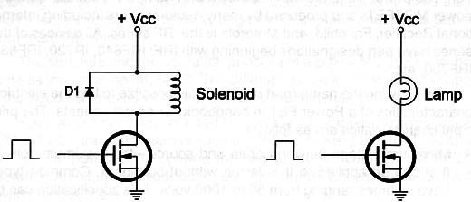
As switches we can find the power FETs controlling solenoids, relays, step motors, and other loads in circuits like the one shown in Figure 2.

When a positive voltage is applied between gate and the ground, the power FET (P channel) turns on and the current flowing across the device powers on the load.
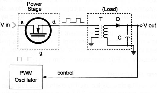
Another important application of power FETs is in Switch-Mode Power Supplies (SMPS) like the one shown in a block diagram in Figure 3.

In this circuit the power FET acts as a switch that opens and closes very fast in a manner so that the pulses of voltage applied to the load can be controlled in frequency and duration.
If the interval or the width of the pulses changes, the amount of ennergy they transfer to the load also changes, and with them, the average voltage.
By using a feedback circuit it is possible to control the width and interval between pulses to keep constant the average voltage applied to a load.
So, in an SMPS exists a circuit that changes the voltage output, controlling the pulse width applied to the power FET to compensate the alterations and keep the output voltage constant.
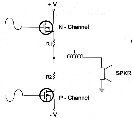
This kind of power supply is found in many types of electronic equipment, such as computers, video monitors, and TVs. In the linear mode, power FETs can be used as audio amplifiers or low-frequency signal amplifiers. A circuit where an audio signal is amplified by a power FET is shown in Figure 4.

Alarms, which are a common type of audio equipment, can use this type of transistor in their output stages driving the loudspeaker with many watts.
High-fidelity (hi-fi) audio amplifiers that use power FETs are high-quality equipment presenting low distortion levels. The power FETs have characteristics similar to the ones found in the old tubes for amplifying low-frequency signals.
Many enthusiasts of the bipolar transistor can’t reproduce the sounds with the same quality found in old tube models.
But, amplifiers using power FETs can present levels of fidelity closer to those found in the tube amplifiers better than the ones of bipolar transistors.
Testing
A simple multimeter can be used to test a power FET. The resistance between the gate and the other terminals must be very high in a good transistor. If a low resistance is measured the transistor has problems.
A low resistance between gate and the other terminals indicates a transistor with losses or a short.


