The coils present opposition to current changes characterized by an electric quantity caIIed inductance The inductance is measured in henry (H) but, the fractions-millihenry (mH) and microhenry (uH) are widely used in practical components. The number of turns and the gauge of wire determine the inductance of an inductor or coil.
Three major classes of coils or fixed inductors are avaiIabIe. They are the filter choke, audio frequency inductor, and the RF inductor or choke. (RF means radio frequency).
Symbols and types
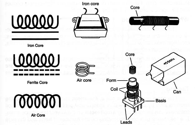
Figure 1 shows some types of coils or inductors the reader can find in electronic equipment.

The presence of a continuous line in the symbol indicates an iron core. The presence of an intermittent line in the symbol indicates a ferrite core. If the line is absent the coil is an air core type.
Adjustable coils can also be found in some applications. These coils have an adjustable core that can be ind or screwed in their form.
Specifications
A. Inductance
The inductance of a coiI is expressed in henry (H) or its fractions. Low valuea in the range of microhenry are found in high-frequency applícations. Values in the range of miIIihenry and henry are found in Iow-frequency circuits and as filter chokes.
B. Core
The nature of the core is an important specification for a coil. Low-frequency and DC coils (filters and audio) use iron cores. High-frequency coils use ferrite and air cores. it is also important to indicate the size and shape of the core. Ferrite toroids or rods are used for high-current chokes and RF applications. Pot cores are an example.
Where they are found
The lower the number of turns, the lower the inductance. Low-inductance coils are used in high-frequency circuits like tuned circuits, filters, etc. High-inductance coils are found in power supply filters, audio circuits, musical instruments, etc.
The use of large inductance coils in a circuit is not common. Because large inductance coils are heavy and expensive components, they are avoided in most projects. Circuits that can simulate inductance using other components are found in some applications.
Testing
The main problem of a coil is the interruption of the wire and the short caused by excess heat or mechanical problems. The test of coil continuity can be done using a multimeter on the lowest resistance scale.
The resistance of a coil, depending on the number of turns and the wire used, should be in the range between 0 and 10,000 Ω. The test for a short is more difficult. Generally, a coil in short, when caused by excess current, presents burning signals such as dark spots and the smell of smoke.


