Note: this article was originally published in Portuguese and translated into English by the autor to be inserted in one of his books.
The basic operation principle of a stepper motor is not much different from that of a dc or ac motor: they are formed by coils and magnets with a moving shaft that moves when power is applied.
The difference is in the way the shaft is moved; they move the rotor by applying power to different coils in a predetermined sequence (stepped).
Steppers are designed for fine control requirements and not only will spin on command but also travel any number of steps per second up to the maximum speed.
Another stepper feature that cannot be matched by common motors is that stepper motors can hold their position and resist turning.
Figure 1 shows the symbol that has been adopted to represent a stepper motor and the appearance of the most common types.
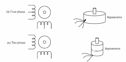
The designer in many cases need not buy expensive stepper motors for these projects, since many of them can be found in good operating condition in old computer diskette drives, printers, and many other devices that have been retired.
How it Works
A stepper motor converts digital information into proportional mechanical movement.
They are different from dc motors, which are controlled by changing the current flowing through them.
Stepper motors are digital in operation stepper motors can be found in three basic types permanent magnet, variable reluctance and hybrid.
The way the windings are organized inside a motor determines how it works.
The most common type is the four-phase stepper motor but there are also two-phase and six-phase types.
Figure 2 shows the most popular version: the four-phase stepper motor.
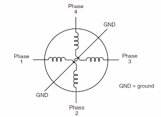
Inside this motor we find four windings. Since each pair of windings has a common connection, this kind of motor can be easily identified by the six wires as shown in Figure 3.
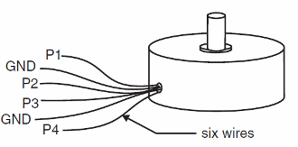
In normal operatiom the common wires are connected to the positive wire of the power supply and the other wires are connected to ground for a short period of time-for as long you want to energize the correspondent winding.
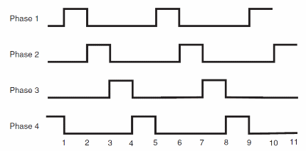
Each time the motor is energized, the motor shaft advances by a fraction of revolution for the shaft to turn properly, the winding must be energized by a sequence of pulses or waves.
For instance, if you energize the windings A, B, C, and D in this sequence, the shaft turns Clockwise.
In the other hand, if you reverse the sequence, the motor turns counterclockwise.
Figure 4 shows the sequence that is nrmally used to energize four-phase stepper motors.
Another way to energize a stepper motor is by applying an on-on/off-off sequence.
This sequence is shown in Figure 5.
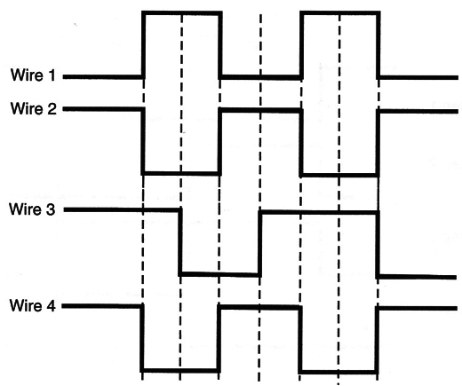
It has the advantage of increasing the drive power of the motor and providing more precise shaft rotation.
Other Common type of stepper motor is the two-phase unit shown in Figure 6.
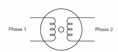
This stepper motor is formed by two coils, as shown in the figure, and it can be easily identified by its four wires.
This type of motor is energized using a different sequence wherein the direction of the current across each widing is considered, as shown by Figure 7.
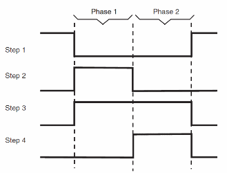
In some types, the -V connection can be replaced by ground.
There are also stepper motors with more phases, e.g. the six-phase stepper motor, but they are not Very common. Motors with more phases are more accurate but also more expensive.
For simple purpose, embracing many applications in projects involving robotics and mechatronics, the four-phase stepper motor is recommended, and most of the projects in this section are designed for this type of motor.
How to Use Stepper Motors
As we had seen, the windings of a stepper motor must be energized properly to achieve correct operation.
This means that, when using a stepper motor you'll need to know not only electrical specifications of the device but the mechanical specifications as well.
The most important specs are described below.
Voltage and Current
Stepper motors are usually rated for 5, 6, or 12 V.
Unlike with dc motors, overdriving the windings of a stepper motor is not recommended.
Overvoltages of more than 30% of the rated voltage can burn the windings.
The Current ratings depend on the application (size and torque). Common types can draw currents in the range from 50 mA to more than 1 A.
The higher the current and voltage, the higher the torque.
When designing a power supply for an application using a stepper moton it is important to consider that the current ratings are given per winding.
Therefore, the power supply must be able to supply at least twice the current per winding, or eight times the current per winding in a four-phase type.
Sequence
Although most stepper motors use one of the two sequences shown before on stepper theory, it is possible to ñnd units that operate differently.
When using such units, it is important to determine the correct operational pulse sequence.
Step Angle
When one pulse from the sequence is applied to the motor it advances one step.
This means that the shaft moves a specified number of degrees, referred to as step angle.
The angle can vary among motor types in the range between 0.8 and 90°.
In a 90° stepper motor four pulses move the shaft one complete tum as shown in Figure 8.
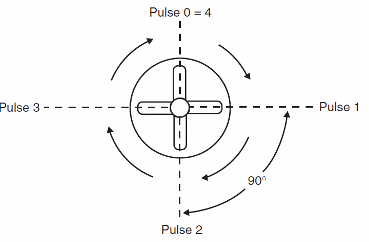
Howeven it is more common to find stepper motors with step angles of 1.8°.
This means that you have to apply 200 pulses to the control circuit to make the motor complete one revolution.
Pulse Rate
The pulse rate determines the speed of the motor.
If you are using a 1.8° step angle motor and you apply 200 pulses per second, this motor will run at l rotation per second or 60 rotations per minute (60 rpm).
Given the step angle, it is easy to calculate the rpm.
The stepper motors are not intended for high-speed applications.
The top recommended speed is in the range of 2 or 3 turns per second, or in the range of 120 to 180 rpm.
It is important to remember that in this kind of motor the torque drops as the speed increases.
Torque
The torque produced by a stepper motor is not high. A typical stepper motor can provide only a few grams per centimeter of torque in operation.
This means that, in applications where high torque is needed, gearboxes must be added.
Since the torque falls at higher speeds, this type of motor is best used in low-speed modes.
Braking Effect
If the current in a winding is maintained after a pulse is applied, the stepper motor cannot continue to tum.
The shaft will be locked as if you applied a brake.
A Circuit that maintains the current in a winding to establish a ñxed position effectively acts as electronic brake in a stepper motor.


