

Teaching Engineering for Young People – I (ART588E)
The LDR
In electronic applications we find many types of light sensors. They are devices that change some electrical property they have when light strikes them. We can say that these sensors function as "electronic eyes" and can be used in a large number of practical applications.
One of the most important is LDR, as we will work on in many of our experiments.
Light Dependent Resistors (LDRs) are light sensitive components, that is, electronic devices that can act on a circuit depending on the light incident on a sensitive surface thereof. LDRs should not be confused with photocells. While LDRs are resistors, whose resistance depends on the intensity of light that impinges on them, thus providing no energy, the photocells convert light (radiant) energy into electrical energy.
Because of their characteristics and low cost, however, LDRs can be used instead of photocells in a myriad of practical applications. In figure 1 we have the symbol used to represent an LDR and the most common aspects with which these components can be found.

We observed that the resistance of this component is very high in the dark, on the order of many megohm, if it reduces to a few tens or hundreds of ohm when it is directly illuminated. In other words, it blocks the current in the dark and lets it pass when illuminated.
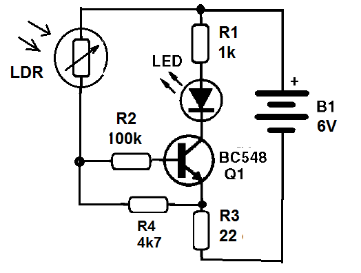
This project shows the action of a LDR (Photo Resistor or Light Dependent Resistor) controlling a transistor from the light it receives. The LDR has a sensitive surface of Cadmium Sulfide (CdS) that has the property of reducing resistance when it receives light, as we studied in the theoretical explanation.
Connected to the base of the transistor, the transistor amplifies the current passing through the LDR and thereby controls the current in the LED. In this circuit, the current in the transistor increases with the intensity of the light so that the LED lights up when the LDR receives light.
Cap the LDR and the LDR goes off. By discovering it so that it receives light, the LED lights up.
Assembly
In figure 2 we have the complete circuit for this experiment.
Mounting on a solderless board is shown in figure 3.

On assembly, observe the position of the transistor and the LED and the transistor. Be aware of the values of the resistors given by the colored bands, depending on the material ratio.
Only connect the batteries after terminals to the assembly and check the connections. In figure 4 we have the photo of the device ready to be used.

Procedure
After checking the assembly, connect the battery holder to the circuit. Receiving the ambient light, the LED must access. Covering the LED so that it does not receive light, the LED should go out.
Put the LED inside a tube and run it from a distance using a flashlight. With this you will have a remote control for your LED, working according to the same principle of remote TV controls.
The difference is in the fact that TV remote controls use infrared emitting LEDs, which we can not see. If the circuit is not very sensitive, change R4.
Used material
Q1 - BC548 - transistor
LED - LED common
R1 - 1 k ohm - resistor - brown, black, red
R2 - 100 k ohm - resistor - brown, black, yellow
R3 - 22 ohm - resistor - red, red, black
R4 - 4k7 ohm - resistor - yellow, violet, red
LDR - Common round LDR
B1 - 4 batteries - 6 V
Miscellaneous:
Matrix of contacts, cell holder, wires, etc.
Astable Flasher
In this circuit, the transistors control the current in the LEDs, so that when each transistor drives the LED connected to its collector it lights up. As the transistors conduct alternately in an astable multivibrator, depending on the capacitors, the LEDs also turn on alternately.
Replace the capacitors to see how they influence the blinking frequency of the LEDs. For the students of the medium and technical courses (STEMers) can be given the formula to calculate the frequency of the flashes and ask that it be calculated for the values of the components used.
Capacitors can also be replaced for others of unequal values in the same circuit, for example 4.7 uF and 47 uF in order to obtain an asymmetric operation for the circuit. In this operation, one of the LEDs stays on longer than the other.
Assembly
In figure 5 we have the complete diagram of the astable multivibrator.

The assembly using the 170-pin solderless board is shown in figure 6.

On assembly, carefully observe the position of transistors and LEDs.
The resistors have their values given by the colored bands, according to the material list. In figure 7 we have the photo of the prototype mounted by the author.

Procedure
Connect the wires of the battery holder to the array of contacts, observing their polarity (colors). The LEDs should flash immediately.
Suggestion
Change the capacitor values to see how they change the frequency of the circuit.
Material list
Q1, Q2 - BC548 - NPN transistors
LED1, LED2 - Common LEDs
R1, R4 - 1k ohm - resistor - brown, black, red
R2, R3- 100 k ohm - resistor - brown, black, yellow
C1, C2 - 4.7 uF - electrolytic capacitors
B1 - 6 V - 4 batteries
Miscellaneous:
Soldrless board, cell holder, wires, etc.
Quiz
- What happens to the flashing of the LEDs if we increase the values of the capacitors used?
- Is it possible to make one of the LEDs stay on longer than the other?
- How can we make this circuit using PNP transistors?
Flasher 4093
In our case, what we do is connect the output of 4093 back to the inputs so that a feedback process occurs.
Starting from the moment the capacitor is discharged, the IC input will be at the low level and with the 4093 inverter the port will be at the high level output.
The capacitor then starts charging through the feedback resistor until the voltage that the 4093 switches is reached, that is, it starts to recognize the voltage at the capacitor as high. At this time, the output goes low and the LED goes out.
With this, the capacitor starts to discharge through the resistor until the 4093 recognizes the capacitor voltage at the low level. A new switching occurs and the CI output goes to high level, with a LED on.
The cycle then continues to charge and discharge the capacitor between the two recognition voltages of 4093 which are different, thanks to what is called hysteresis. It is this difference that allows you to use the 4093 in an oscillator circuit like this.
Assembly
In figure 8 we have the complete circuit of the flasher that drives an LED using the integrated circuit 4093.

The circuit assembly in the contact array is shown in figure 9.

When assembling, it is important to note the position of the integrated circuit and to dock it, do it very carefully so that all the pins are aligned with the holes.
When we press the integrated circuit all the pins must fit effortlessly. We should also note the position of the LED and the polarity of the electrolytic capacitor.
Procedure
When plugging the wires of the battery holder, observing the polarity, the LED should start blinking immediately. Test with other capacitor values and also with other R1 values. Take care not to use R1 less than 1k.
In figure 10, the photo of the assembly.

Material list
CI-1 - 4093 - integrated circuit
LED1 – common LED
R1 - 100 k ohm - resistor - brown, black, yellow
R2 - 1 k ohm - resistor - brown, black, red
C1 - 4.7 uF - electrolytic capacitor
B1 - 6 V - 4 batteries
Miscellaneous:
Solderless board, support of batteries, wires, etc.
Quiz
- What happens to the LED flashes if we increase the value of the resistor connected to the capacitor?
- Is it possible to mount four independent flasher with this same integrated circuit?
- What are the voltages that can be used to power this circuit?
Electroscope with the 4093
The gates of the 4093 integrated circuit are extremely sensitive and can even operate with the small static charges accumulated in the bodies.
Thus, simply rub an object like a ruler or another plastic into a tissue so that it charges of electricity and approaching a wire connected to the input of the 4093 terms induced enough voltage for it to switch the circuit.
In this way, an LED on its output will turn on or off according to the polarity of the body charge that we approach the wire used as an antenna.
This circuit acts as an electroscope which is an instrument used to check if a body contains electrical charges.
The detected charges are static charges obtained, for example, when we rub two insulators.
See in the physics books what is the process of electrification to better understand what happens in this case.
Assembly
In figure 11 we have the complete diagram of the electroscope.

Figure 12 shows how to make your assembly in the solderless board.

When assembling, it is important to note the position of the integrated circuit and to dock it, do it very carefully so that all the pins are aligned with the holes.
When we press the integrated circuit all the pins must fit effortlessly.
Observe the position of the LED and the values of the resistors used.
The sensor consists of a length of 10 to 15 cm long stranded wire fitted into the corresponding hole in the contact die.
In figure 13 we have the photo of the assembly.

Procedure
Rub a pen, ruler, or comb on your clothing and approach the electroscope's sensing antenna, but do not touch it. When moving the electrified object, the LED should flash indicating the presence of loads.
Experiment with various objects from insulation materials such as fabrics, plastics, glass, etc.
Suggestion
Adapt this circuit to trigger a sound oscillator instead of turning on the LED, based on the oscillators triggered from previous designs.
Material list
CI-1 - 4093 - CMOS integrated circuit
LED - ordinary LED of any color
R1 - 1 k ohm - resistor - brown, black, red
B1 - 6 V - 4 batteries
Miscellaneous:
170-point solderless board, wires, battery holder.
Quiz
"Why do not we have to lean the charged body on the antenna so the circuit detects its charge?"
- What friction electrification?
- Why the LED can either light up or turn off in the presence of charges on a body?


