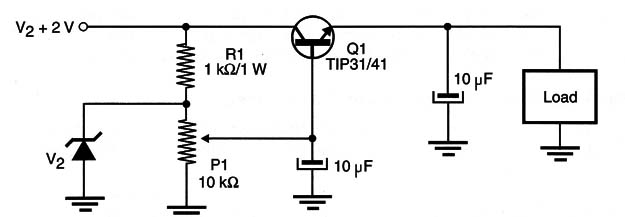
The variable power supply shown in Figure 1 is a traditional configuration using a zener diode as voltage reference.

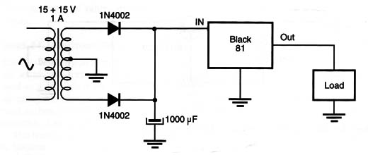
This circuit can also be used in applications such as a workbench power supply used to test circuits and devices that require currents up to 1 A. You can add a rectifier stage and a transformer as shown in Figure 2 to convert it into a complete power supply.

The presence of the zener diode is important in defining the voltage range supplied by the circuit. This range starts at 0 V and has as upper limit defined by the zener diode voltage plus 0.6 V (the voltage drop in the emitter-base junction of the transistor). For instance, if you use a 12 V zener diode, your supply will provide voltages in the range between 0 V and 12.6 V.
Using a 6 V x 400 mW diode, you can control the speed of 6 V loads without the risk of burning out the motor with excess voltage, even if the input is much more than 6 V. The recommended input voltage for this configuration is at least 2 V higher than the nominal voltage in the output and twice this voltage. For instance, if the load is a 6 Vdc motor, the recommended input for this application is between 8 and 12 V.
The transistor is chosen according the motor current, and any 400 mW or 1 W diode can be used for output currents up to 1 A. The transistor must be mounted on heat sink.
Zeners in the range between 3 V and 12 V can be used. Resistor R1 can be experimentally valued in the range between 470 Q and 2.2 k ohm to allow the circuit to cover the desired voltage range.


