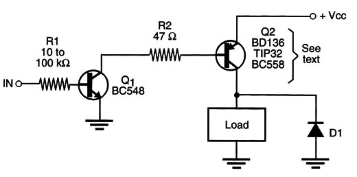
In the block shown by Figure 1, we have two transistors (one NPN and the other PNP) directly coupled to form a high-gain stage for driving loads.
Q1 is an NPN transistor. Any general-purpose NPN silicon transistor such as Lhe BC548, 2N3904, 2N2222, or others can be used for this task. Q2 depends on the current across the load. For loads up to 50 mA, such as small relays, magnets, solenoids, lamps, and motors, a BC558 can be used.
For large currents, you can use the BDl36 (1 A) or TIP32 (3 A). A few microamperes in the input are necessary to drive The loads. The load is on when the input is positive.
Complementary Driver (II)
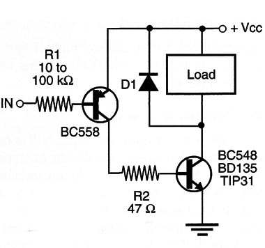
This circuit (Figure 2) also uses complementary transistor, but the input (Ql) is a PNP, and the output (Q2) is a PNP.

For Q1, you can use the BC558 or any equivalent. For Q2, you can use the BD135 (l A) or the TIP32/TIP42 (up to 3 A). The load is on when the input is low (to ground). Only few milliamperes are necessary to drive the loads, which allows the use of resistive sensors such as LDRs.


