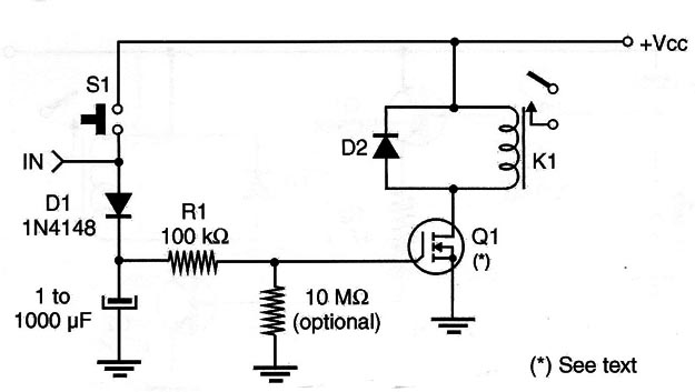
This circuit can be used to keep a relay closed for very long time intervals. We can think of it as a lock or holding circuit that is suitable for many applications in robotics and mechatronics.
The circuit, for instance, can be used to stall a system or a robot when a particular sensor is activated, disabling the power supply or the propulsion system.
The circuit uses a power MOSFET and can drive not only relays but other loads such as motors, solenoids, and circuits. The circuit is shown in Figure 1.

When S1 is activated or a positive control pulse is applied to the input IN, capacitor C1 is charged. Due the very high input impedance of the power MOSFET input, the capacitor maintains its charge (Dl is used if an external circuit is plugged to the input, avoiding the discharge of C1).
The circuit will remain activated as long as the capacitor keeps its charge. A second switch can be placed in parallel with the capacitor to disarrn the circuit.
An important point to consider when assembling this circuit is that capacitor C1 must be of high quality, without leakage. Polyester types from 1 to 10 µF are recommended.
We also must consider that humidity in the air can contribute to capacitor discharge. Keep all wires between the capacitor and gate short in this application to avoid charge leakages into the air.
Any power FET can be used in this application, and the relay or load depends only on the voltage of the power supply.
If used with a microcontroller S1 is not used and the output voltage must be enough to charge the capacitor with 5 V at least to keep the MOSFET on.


