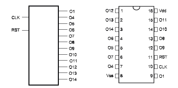
Description: This device contains a 14wstage binary counter that counts upward. The circuit can be used as a frequency divider up to 18,884. The circuit has no outputs for the second and third stages.

Pin Names:
Vdd - Positive Supply Voltage [BV to 15V]
Vss - Ground
Q1, 03, Q4, 04, Q6, Q7, Q8, Q9, Q10, Q11, Q12, Q13, Q14 - outputs
RST - Reset
CLK - Clock or Input
Truth Table: none
Operation Mode:
RST is connected to the ground in normal applications.
The circuit advances one count at each negative input pulse. The division is made by a number corresponding to a power of 2 of the considered output. For instance, in the output Q4 we have a division by 24= 18. The maximum division is found in the 14th output [014] where the division quotient is 214= 16,884.
To force all the outputs to the “0” level make the RESET input positive.

Other Devices:
The 4040 is a divider with 12 stages dividing for values up to 4,096.
The 4080 is a divider with 14 stages dividing for values up to 18,384.
The 4060 has an internal osciIIator.
Applications:
Timers
Counters
Frequency Dividers
Time Delay Applications
Observations:
This device is a rippIe counter. When setting the time, incorrect counting can result.


