

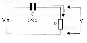
The capacitive reactance of a capacitor can be used in a voltage divider from which we can design a transformerless power supplies as the one shown in figure bellow Supposing a resistive load we can calculate C and R using the next formulas:
Formula 1
Calculating R:
R = V / I
Where:
V is voltage across the load in volts (V)
I is the current in the load in amperes (A)
R is the load resistance in ohm (Ω)
Note: V and I are root mean square values (rms).
Formula 2
Impedance:
Z = Vin / I
Where:
Z is the circuit impedance in ohm (Ω)
Vin is the input voltage in volts (V)
I is the total circuit current or load current in amperes (A)
Formula 3
Capacitive reactance:
Where:
Xc is the capacitive reactance of the used capacitor in farads (F)
Z is the circuit impedance in ohm (Ω)
R is the load resistance in ohm (Ω)
Formula 4
Where:
C is the capacitance in microfarads (uF)
π is 3.1416
f is the AC power line frequency in hertz (Hz)
Xc is the capacitive reactance in ohm (Ω)
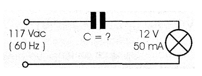
Application example:
Determine the capacitance of C in the circuit shown in figure 77 to power the 12 V x 50 mA lamp from the 117 V x 60 Hz power line.
Data:
V = 12 V
Vin = 117 V
I = 0.02 A (20 mA)
f = 60 Hz
C = ?
a) Calculating R (formula1)
R = 12/0.02 = 600 Ω
b) Determining Z (formula 2)
Z = 117/0.02 = 5 850 Ω
c) Now, Xc can be found using formula 3:
Xc = √[(5,850)2 - (600)2] = √[31.9 x 10⁶ - 0.36 x 10⁶] = √[31.56 x 10⁶ ] = 5 618 Ω
d) Finding C (formula 4):
C = 106 / (2 x 3.14 x 60 x 5,618) = 106 / 2.116 x 106 = 1 / 2.116 = 0.47 µF or 470 nF


