

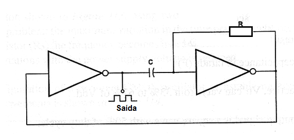
The simplest configuration for a two-gates oscillator or astable multivibrator using CMOS integrated circuits is shown in figure bellow. Any gate that can be wired as inverter can be used in this application. The basic application recommends the use of a 4060 IC but the 4001 and 4011 wired as inverter are also suitable.
Formula 1
Period:
Where:
T is the period in seconds (s)
R is the resistance in ohm (Ω)
C is the capacitance in farads (F)
Vdd is the power supply voltage in volts (V)
Vtr is the transfer voltage in volts (V)
Formula 2
Reduced formula to calculate the period:
By letting Vtr = 0.5Vdd, formula 122.1 can be simplified:
T = 1.39 x R x C
Where:
T is the period in seconds (s)
R is the resistance in ohm (Ω)
C is the capacitance in farads (F)
Obs:
a) In practice, Vtr can vary from 33% to 67% of Vdd.
b) the output signal is a square wave with 50% of duty cycle.
Formula 3
Frequency (short form):
f = 1 / (1.39 x R x C )
Where:
f is the frequency in hertz (Hz)
R is the resistance in ohm (Ω)
C is the capacitance in farads (F)
Application Example:
Calculate the frequency of a CMOS astable multivibrator with a configuration shown in figure 113 where a 10 nF capacitor is used with a 100 kΩ resistor.
Data:
C = 10 nF = 10 x 10-9 F
R = 100 x 103 Ω
Using formula 3:
f = 1 / (1.39 x 100 x 103 x 10 x 10-9)
f = 1 / (1.39 x 10⁻³)
f = 0.719 x 10³
f = 719 Hz


