

The configuration shown in MA123E using two gates of a CMOS integrated circuit as inverters has a problem: the maximum variation in the time period can be only as high as 9%. By adding a resistor (Rs) the frequency comes independent from the supply voltage and the time-period variations with the power supply voltage is reduced.
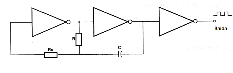
The basic configuration of a Two-Gate CMOS oscillator or astable multivibrator with the described improvements is shown in figure bellow.
Formula 1
Exact period:
Where:
T is the period in seconds (s)
R is the resistance of R in ohm (Ω)
C is the capacitance in Farads (F)
Vdd is the power supply voltage (V)
Vtr is the transfer voltage (V)
Note: a) Rs should be 10 times the value of R.
b)Minimum value recommended to R is 50 kΩ
c) C must be greater than 1 nF.
d) Vtr in practice can vary from 33% to 67% of the power supply voltage (Vdd).
c) The output is a square wave with 50% of duty cycle.
Formula 2
Simplified formula (making Vtr=0.5xVdd)
T = 2.2 x R x C
Where:
T is the period in seconds (s)
R is the resistance of R in ohm (Ω)
C is the capacitance of C in farads (F)
Formula 3
Frequency (short form):
f = 1 / (2.2 x R x C)
Where:
f is the frequency in hertz (Hz)
R is the resistance in ohm (Ω)
C is the capacitance in farads (F)
Application example:
In the circuit shown in figure above, R is a 10 kΩ resistor, Rs a 100 kΩ resistor and C a 0.05 µF capacitor. Determine the frequency or the produced signal.
Data:
R = 10 x 103 Ω
C = 0.05 x 10⁻⁶ F
f = ?
Using formula 3
f = 1 / ( 2.2 x 10 x 103 x 0.05 x 10-6 )
f = 1 / ( 1.1 x 10⁻³ )
f = 0.909 x 10³
f = 909 Hz


