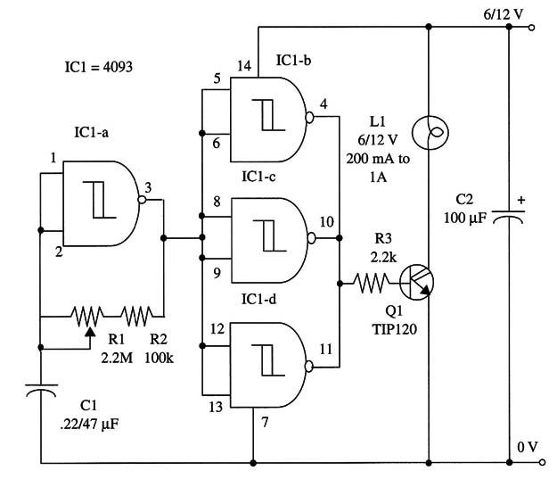
his device will flash small 6 or 12 V lamps in a rate adjustable between 0.1 and 2 Hz by a potentiometer. A Darlington power transistor will drive lamps with current rates up to 1 A.
The device can be used as a component of alarms or in cars, trailers, and so on. It is powered from 6 or 12 V batteries.
C1 can be altered to change the frequency range. High values will give lower flash rates. Values up to 2.2 µF can be used for experimentation.
A schematic diagram of the device is shown in 1.

IC1 - 4093 CMOS integrated circuit
L1 - 6/12 V, 200 mA to 1 A incandescent lamp (see text)
Q1 - TIP120 N PN Darlington transistor
R1 - 2,200,000 Ω, 1/4 W, 5% resistor
R2 - 100,000 Ω, 1/4 W, 5% resistor
R3 - 2,200 Ω, 1/4 W, 5% resistor
C1 - 0.22 or 0.47 µF ceramic or metal film capacitor
C2 - 100 µF, 16 WVDC electrolytic capacitor


