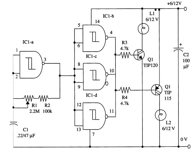
The duty cycle is 50 percent, and the frequency range is between 0.1 and 5 Hz.
C1 can be altered, as in the other projects, to change the frequency range. Values up to 2.2 11F can be used experimentally, depending on the intended applications.
A schematic diagram of the flasher is shown in Fig. 1.

You can also High Power White LEDs with series resistor according the current drained by them. Values between 12 Ω and 100 Ω can be experiments.
IC1 - 4093 CMOS integrated circuit
Q1 - TIP120 N PN Darlington power transistor
Q2 - TIP115 PNP Darlington power transistor
L1, L2 - 200 mA to 1 A lamps (see text)
R1 - 2,200,000 Ω potentiometer
R2 - 100,000 Ω, 1/4 W, 5% resistor
R3, R4 - 4,700 Ω, 1/4 W, 5% resistors
C1 - 0.22 to 0.47 µF ceramic or metal film capacitor
C2 - 100 µF, 16 WVDC electrolytic capacitor


