

Features
Power supply voltage: 3 to 12 Vdc
Range: 150 to 1,500 ft (according to the power supply, see text)
Operating frequency range: 88 to 108 MHZ
As with the TEL053 project, this circuit is intended for wireless monitoring of remote events using a common FM receiver. This circuit is different from the first version in that, rather than sending beeps at a repetition rate that varies with the resistance of the sensor, this version sends constant beeps when the sensor is triggered.
Many types of sensors can be used with this circuit, as suggested by the following applications:
Water sensor. The circuit is triggered when water falls on a sensor. There are two ways to trigger the circuit: When the water level drops below a predetermined value or when the water level rises above a certain value. The circuit can be used to control the level in a reservoir or to detect rain. For this application, the sensor is formed by two bare wires separated at a distance of one inch, or two metal screens with a salted tissue between them.
Position sensor. The movement of objects, doors or windows closing or opening, and other displacements of people, objects, and animals can be detected with an appropriate sensor. The recommended sensor can be a blade magnetic switch, microswitch, reed switch, or any other type.
Light sensor For this application, the sensor can be a light dependent resistor (LDR) or a photoresistor (or CdS cell, as it is also called). The circuit can detect when a light is turned on or off, when a person enters in a room, or when a substance changes its transparency due to a chemical reaction.
Temperature sensor. NTCs, PTCs, or diodes can be used to detect temperature changes. The circuit will send a signal when the monitored temperature falls below or rises above a preset value.
Other sensors. As appropriate to the application, the reader will discover that other sensors can be used, some of which can be home made. For instance, pendulum sensors can detect when an object is shaken. It is up to the reader’s imagination to create the necessary sensor for an application.
How It Works
Figure 1 shows a block diagram of this circuit. With reference to this diagram, we will explain how the circuit works.

The first block is a monostable multivibrator activated by the sensor. The objective of this circuit is to produce a constant-duration pulse, independent of the time in which the sensor is activated. This kind of action is important for applications where the sensor is activated by short time intervals.
The pulse duration can be adjusted to values between several seconds and live minutes with the components values shown in the diagram. The time values in this range are adjusted by P1. If the reader wants longer time intervals, both P1 and C1 values can be increased. P1 values up to 1,500,000 ohm and to C1 values up to 2,200 µF are permitted, extending the maximum time interval up to an hour.
The integrated circuit ICl, which acts as the monostable, is triggered when pin 2 is driven to a low level. This means that, to trigger the circuit, point X1 must be connected to ground, or at least to a voltage corresponding to one-third or less of the power supply voltage.
Note that Rx keeps this input (pin 2) at the high level, and so the sensor must form a voltage divider with this component. Therefore, to trigger the circuit on, the value of Rx must be carefully chosen to put the voltage at pin 2 below one-third of the power supply voltage at the triggering point.
A simple rule to adopt when choosing Rx is that this component must have twice the sensor resistance value when the circuit is to be triggered. For instance, if the sensor is an LDR with a resistance range between 10,000 and 1,000,000 ohm in the proper light range, a resistor of 100,000 Q can be used, assuming that the desired level to trigger the circuit will occur when the LDR presents a 50,000 ohm resistance.
If low-level light sources are used, the value of Rx must be increased to 470,000 ohm. This means that the circuit will be triggered on when the LDR resistance falls to approximately 220,000 ohm.
For easy adjustment, the reader can add a potentiometer in series With Rx. A 1,000,000 ohm component is suitable.
The described monostable stage controls a second block, which also uses a 555 integrated circuit. But, in this case, the IC is wired as an audio oscillator.
The audio oscillator has its frequency determined basically by C3 and adjusted by P2. The tone can be adjusted to frequencies in the range between 500 and 5,000 Hz. The circuit is off until the output of the first block goes to the high level. This occurs only when the first block is triggered on. Therefore, an audio tone is produced and applied to the input of a high-frequency stage, which acts as a transmitter.
The transmitter is formed by one transistor in the common coníiguration found in many other projects described in this book. The produced frequency is in the FM range, but if the reader has a VHF receiver, it is possible to find a less congested band in that range for operation of the circuit. By changing the coil, it is possible to alter the frequency as shown in the following table.
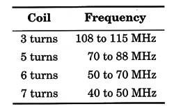
These values are not exact, as the components (particularly the trimmer capacitor) have large tolerances in their values. Therefore, the reader must find the correct number of turns experimentally according to the intended transmission frequency.
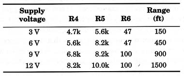
The transistor and the power supply determine the output power and therefore the range. Using a BF494 transistor, the circuit can be powered from 3 to 6 V power supplies; using a 2N2218 device, the circuit can be powered from a 9 or 12 V supply.
The following table gives the components, values for the several usable voltages to power the circuit and the range achieved in each case.
The antenna also affects performance, and pieces of rigid plastic-covered wire between 10 and 40 in. in length can be used for this task. It is important to iind the best place to connect the antenna to the coil, as described for many transmitters in this book.
Assembly
Figure 2 shows a schematic diagram of this transmitter.

Notice that some components have values that depend on the power supply voltage and the output transistor. It is also important to observe that, for the 3 V version, a bipolar 555 will not operate as expected. This component must be replaced by a CMOS 555 or a TLC7555 as specified.
The components are placed on a printed circuit board as shown in Fig. 3.

For the 12 V version, the transistor must have a small heat sink.
The specifications for resistors and capacitors are given in the parts list. Note that there are some ceramic capacitors that must not be replaced by other types.
The coil is formed by four turns of AWG 18 to 22 enameled wire or common rigid plastic-covered wire wrapped around a pencil as a reference (diameter 1 cm). The tap to use for the antenna connection must be found experimentally.
Any trimmer capacitor with capacitance ranges between 2-20 and 4-40 pF can be used. Porcelain or plastic types are suitable. The reader only has to observe the terminal placement if it becomes necessary to make changes in the printed circuit board layout.
The power supply choice depends on several factors as suggested below:
1. For short-range monitoring and short-time operation (up to 20 min), use two or four AA cells for a 3 or 6 V version.
2. For short-range monitoring and extended-time operation (up to 3 hr), use two or four C or D cells for a 3 or 6 V version.
3. For short-range monitoring and continuous operation, use a 3 or 6 V power supply.
4. For long-range monitoring and short-time operation (up to 20 min), use six to eight C cells for 9 to 12 V versions.
5. For long-range monitoring and extended-time operation (up to several hours), use a car or nicad battery for a 12 V version.
The Sensors
As described previously, the circuit can operate with several different types of sensors, depending on the event to be detected. Listed next are the principal sensors that can be used with this circuit.
Contact Sensors
Many types of sensors can be used to trigger the circuit by the contact or touch of a person, animal, or object. A push button, a pendulum sensor, and a reed switch are samples of sensors that can be used for this task. Some of these sensors are shown in Fig. 4.

The recommended range of values for Rx, when using these sensors, is between 4,700 and 47,000 ohm.
Such sensors can be used to detect when a cage door is opened or closed by an animal or when objects are moved. The sensor can be mounted in the same box used to install the transmitter or wired to it by a long, flexible wire. It is not necessary to use shielded cables.
Water Sensors
The appropriate sensors for water detection are shown in Fig. 5.

The sensors as wired in two cases (Fig. 5a and b) are indicated to detect changes in water level. This configuration can be used to detect when the water level in a reservoir falls or rises to a predetermined point. Note that the circuit is triggered when the water touches the Wires, closing the circuit.
The third sensor (Fig. 5c) is used to detect any presence of water. This sensor can be used to detect when a rain begins or to detect plumbing leaks. The two-wire configuration can also be used to detect when a flower pot needs water.
The sensitivity offered by circuits that use this sensor can be increased with the circuit shown in Fig. 6.

This circuit uses a sensitivity control, and the capacitor value depends on the speed at which the events occur. You can experiment with values between 470 nF and 10 µF to find out which is appropriate for a particular application.
One suggested application for this circuit is detecting a wave when it passes by the sensor. The circuit can be used as a swimming pool alarm, detecting when someone falls accidentally into the water.
Light Sensors
The best sensor for this application, because of its sensitivity and low cost, is the LDR or light dependent resistor (CdS cell). The circuit used to wire this sensor to the event transmitter is shown in Fig. 7.

Rx is replaced by the potentiometer or the LDR, depending on the version. In the first circuit, the sensor triggers on the transmitter when light falls onto its sensitive surface. The potentiometer adjusts sensitivity as appropriate to the ambient light level.
The second version is triggered when the light falling onto the sensor is cut off or reduced. Here, too, sensitivity is adjusted using the potentiometer.
If the light changes to be detected are very short in duration, the circuits shown in Fig. 8 are more appropriate. One of the circuits triggers on the transmitter when a short pulse of light falls onto the sensor. The other circuit triggers the transmitter when a short light outage occurs.

In all cases, directivity and sensitivity can be increased if the LDR is mounted inside an opaque tube with a convergent lens placed in its opening.
Temperature Sensors
A negative temperature coefficient (NTC) or positive temperature coefhcient (PTC) resistor can be used to detect temperature changes. The circuits are basically the same as the ones used with other resistive sensors, such as the LDRs.
Figure 9 shows some circuits that can be used with these sensors.

Another sensor that can be used to detect temperature changes is a reverse-biased silicon diode. A transistor must be used to amplify the small temperature-dependent current that flows by this device. Note that circuits using NTCs act in the opposite manner of PTC-based circuits.
Other Sensors
A piece of conductive foam and two metal plates can be used to make a pressure sensor as shown in Fig. 10.

An appropriate source of this foam is the packíng material used to transport sensitive CMOS integrated circuits, dissipating static discharges that can destroy them.
Another sensor is shown in the same figure, using an LDR and a light source (a small incandescent lamp). This sensor can be used to detect When the transparency of a substance changes due to a chemical reaction.
Conclusion
The reader who makes scientific field experiments can find many uses for this project. If you install the transmitter in a plastic box and keep a stock of sensors on hand, you will be ready to perform a range of experiments using remote sensors whenever the need arises.
Adjustments
To use the circuit, the main required adjustment is performed using CV, with Which you tune the, circuit to a free point in the FM band. The other adjustments depend on the sensor and are implemented to find the most appropriate sensitivity for the application.
Semiconductors
IC1, IC2 555 integrated circuit, timer
Q1 BF494 or 2N2218 high-frequency NPN silicon transistor (see text)
Resistors (1/8 W, 5%)
R1, R2 10,000 ohm - brown, black, orange
R3 4,700 ohm - yellow, violet, red
R4, R5, R6 values according supply voltage and transistor (see table)
P1, P2 100,000 ohm - trimmer potentiometers
Capacitors
C1 10 to 100 µF/12 WVDC, electrolytic
C2, C4, C5 0.01 µF, ceramic
C3, C8 0.1 µF, ceramic
C6 4,700 pF, ceramic
C7 . 4.7 pF, ceramic
Additional Parts and Materials
L1 coil (see text)
CV 2-20 to 4-40 pF trimmer capacitor (see text)
S1 SPST toggle or slide switch
B1 3 to 12 V power supply (see table and text)
Printed circuit board, plastic box, battery holder, sensors, antenna, wires, etc..


