

You can extend the project by using two chips, and you will be able to continuously monitor the audio output power of both sides of your stereo system. This will permit to you properly set the balance control for equalized outputs.
Transformer T1, in the input, isolates the circuit from the ampliiier, providing the necessary safety from shorts and shocks.
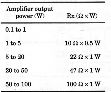
The circuit can be used with amplifiers ranging from 0.1 to 100 W. RX is chosen according the output power of the amplifier. Values are giving in Table 1.
Table 1 Amplifier Output vs. Rx
Resistors R3, R4, R5, and R6 determine the dynamic range in which the circuit operates. Variations in these components can be made to match the action of the LEDs with logarithmic or other scales.
R1 adjusts sensitivity and, depending on the application, you can set the value to a fixed point using a trimmer potentiometer.
The circuit can be powered from power supplies ranging from 6 to 12 V. Resistors R7 to R10 determine the light level of the LEDs and can be altered according to the power supply voltage.
A schematic diagram of the Simple Bargraph is given in Fig. 1.

Audio signals come from the loudspeaker output in the amplifier. Any small transformer with a 117 Vac primary, a secondary rated from 5 to 12.6 V, and currents between 100 and 500 mA can be used in this project.
Proper positioning of the polarized components (LEDs, diode, and electrolytic capacitor) must be observed.
R1 adjusts sensitivity, and R6 adjusts the threshold of operation (i.e., when the first LED turns on).
Bass response is given by C1. You can vary this component in the range given in the schematic diagram to achieve the best performance.
Two units can be mounted to monitor a stereo system. Each unit is then Wired to a channel of the stereo amplifier.
IC1 4093 CMOS integrated circuit
D1 1N4148 general purpose silicon diode
LED1 to LED4 Red common LEDs
T1 Transformer, 117 Vac to approx. 5 to 12 V, 150 mA to 500 mA (Radio Shack 27 3-1385, 12.6 V, 300 mA is suitable for this project-see text)
Rx Value according amplifier output power (see Table 1)
R1 10,000 ohm potentiometer
R2 47,000 ohm, 1/4 W, 5% resistor
R3 47,000 ohm, 1/4 W, 5% resistor
R4 33,000 ohm, 1/4 W, 5% resistor
R5 22,000 ohm, 1/4 W, 5% resistor
R6 220,000 ohm potentiometer or trimmer potentiometer
R7 to R10 1,000 ohm, 1/4 W, 5% resistors
C1 0.047 to 0.47 µF ceramic or metal film capacitor (see text)
C2 100 µF, 16 WVDC electrolytic capacitor


