Note: this circuit is part of my book Electronic Projects from the Next Dimension (Newnes 2001)
How It Works
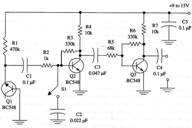
Q1 is the noise source or generator and is the same used in the previous project.
You can use any silicon diode or silicon general-purpose NPN transistor.
Transistors Q2 and Q3 are the core of the amplification stage, increasing the noise amplitude to values up to half a volt, which is enough to drive external circuits such as amplifiers. As in the previous project, if S1 is closed, the circuit can be used as a pink noise generator.
The circuit can be powered from a 9 V battery or a power supply that provides voltages between 9 and 12 V, such as the one suggested for ART078E.
Depending on the transistor used as a noise source, the circuit may not operate with 9 V supplies and may require a 12 V supply. In this case, you can use eight AA cells as in the previous project. The current drain is very low, extending the battery life if a battery is used.
Assembly
The circuit of the white (and pink) noise generator is shown in Fig. 1.

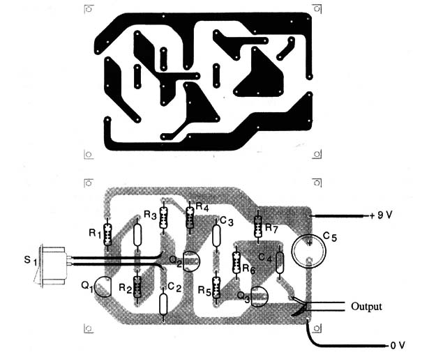
Placement of the components on a small printed circuit board is shown in Fig. 2.

An alternative mounting process is the one that uses a terminal strip as the chassis. The use of discrete parts such as transistors, resistors, capacitors, and other components (i.e., no IC) allows the reader to choose this solution for mounting: For experimental purposes, the reader can also mount the circuit on a solderless board.
The circuit is not critical, but special care must be taken with the output cable. It must be shielded to avoid hum (a 60 Hz signal that can be picked up from the power supply line).
This care must be doubled if the circuit is mounted on solderless board or if the circuit is powered from the ac power line.
The circuit and power supply can be housed in a small plastic box. A metallic box is also suitable, with the advantage that it will act as an electromagnetic shield, cutting external noise and hum.
Using the Circuit
Plug the circuit to the microphone input of a tape recorder or an audio amplifier as in project described I n article ART078E. In the first case, the noise is applied directly to the tape.
In the second case, the amplifier with a loudspeaker can be used to fill an ambient with white and pink noise. The circuit can also modulate transmitters, as will be described in the experiments involving radio waves.
The noise level is adjusted by the volume control in the amplifier. The circuit can be powered by battery, AA cells, or the same power supply recommended for the previous project.
Suggestions
The same alterations suggested in ART078E can be used in this project.
R6 can also be varied between 330 k ohm and 1 M ohm to alter the circuit gain.
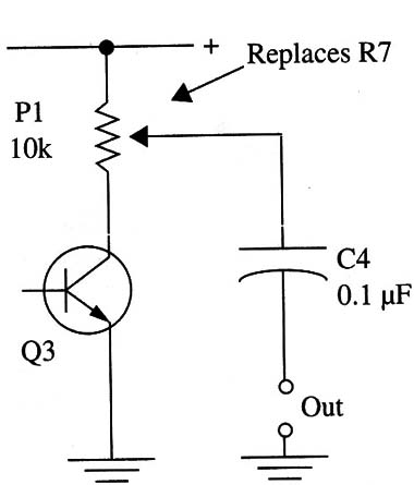
A 10 k ohm potentiometer can be added to the output of the circuit as a volume or amplitude control. The wiring of this control is shown in Fig. 3.

It is important when the signal is injected directly into the input of a tape recorder to avoid saturating (overdriving) the circuits.
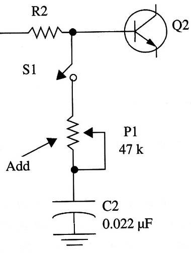
Try using a dynamic filter to the noise frequency spectrum as shown in Fig. 4.


