This project provides a simple but interesting idea for a competition involving mechatronics and the skills of the readers who like this kind of challenge.
The basic idea is to construct a timer using only mechanical parts that turn on a lamp after a predetermined time interval. The winner might be the person who has the project With the highest accuracy and the most imaginative solution.
The circuit is very simple, and the same configuration can be used in many other projects that could be ideal for a competition organized by students or other groups.
Objectives
Build a mechanical timer that triggers an electronic circuit for a precise time period.
Find solutions for the highest accuracy.
Study the movements of mechanical parts.
Participate in a competition involving skills in mechatronics.
Use the circuit to study cross themes of middle school and high school curriculum.
Add the basic configuration to create other automatic devices.
How it Works
This project can be divided into two parts: the mechanical part and the electronic part.
Mechanics
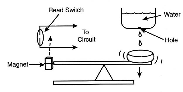
The basic idea is to trigger a circuit using a magnet with a reed switch.The mechanical parts must move in a manner that passes the magnet near the reed switch, thus triggering the circuit for a preprogrammed time period, as suggested by Figure 1.

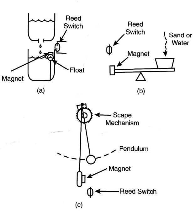
The challenge is to design a mechanical system that places the magnet near the reed switch only during the preprogrammed time. Many solutions can be adapted such as the ones shown in Figure 2.

Figure 2(a) shows a simple idea using hydrotronics, or the use of hydraulics combined with mechanics and electronics. The water flows slowly from one reservoir to another, causing a float on which a magnet rests to rise. When the float reaches the reed switch, the circuit is triggered.
Figure 2(b) shows a different solution, one using a lever. In this case, the increasing weight in one side causes the other side to rise, thus aligning the magnet with the reed switch after the programmed time period.
Figure 3(c) shows yet another interesting solution using a stepped rotary motion system driven by pendulum.
Of course, the imagination of the reader can find other solutions such as antique clock mechanisms driven by springs and so on.
Electronics
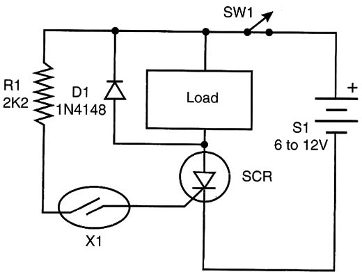
The electronic portion of the circuit is very simple. The reed switch can’t control large loads because in many parts the maximum current is limited to 200 mA or even less. Thus, we used the reed switch to trigger a silicon controlled rectifier (SCR), as shown in Figure 3.

This circuit latches when triggered and powers any load wired to its anode.
You can power a 6-volt lamp, a buzzer alert, an electronic siren, a relay, or even a small motor driving another appliance. To reset the circuit, turn off the switch (SW1) that controls the power source and turn it on again after removing the magnet from the reed switch.
It is important to remember that, when the SCR conducts, a voltage of about 2 volts is observed between the anode and cathode. Therefore, when 6-Volt loads are driven, it is important to compensate for this voltage fall by adding 2 or 3 volts to the supply. A 9-volt supply is recommended in this case.
Obs. You can also power a LED with a 330 ohm series resistor.
How to Build
The schematic for the electric timer is shown in Figure 3. No critical parts are used, and the reader is free to make changes in the original project.
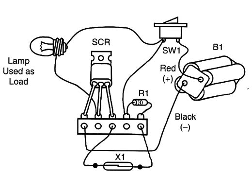
Because it is a very simple configuration, the reader can mount it using a terminal strip to hold the components, and Figure 4 shows this mounting.

When mounting, take care positioning the polarized components such as the SRCs, diodes, and power supply.
The wire to the sensor can be long, up to 10 meters if necessary, and does not need to be shielded or insulated. The diode is used only if the load is inductive such as with relays, motors, and solenoids. Lamps and electronic circuits donlt require the diode.
Testing and Using
Testing is very simple. Insert the cells in the holder and turn on the circuit acting on SW1. The load will remain off.
Now place the magnet near the sensor. The SCR will be triggered, and the load will turn on. To reset the circuit, remove the magnet and place it far away from the sensor. Then open and close SW1 again. If everything functions as described, you can use the circuit in your challenge.
SCR – TIC106, C106, or MCR106 common SCR
D1 - 1N4148 (only for inductive loads)
R1 - 2.2 k x 1/8-watt resistor (red, red, red)
SW1- On/off SPST switch
X1 - Reed switch
Load - Any 6- or 12-volt load (according to the power supply voltage)
B1 - 4 to 8 AA cells or power supply from the AC power line (6 to 12 volts)
Terminal strip, solder, wires, magnet, etc.
Other Ideas
The challenge proposed by this project is perfect to use in discussions of principles from physics, mechanics, and mathematics. The teacher can associate the challenge with the following themes:
Pendulum
Time measurements
Levers
Hydraulics
Gears


