

In the power supply design, power loads control such as motors, solenoids, heating elements is interesting to have a device that simulates the load supplied, but can be adjusted to a current drawn over a wide range of values.
Connecting this device to the output and adjusting the current drawn can check the performance of the tested circuit, if voltage drops occur, instability or other problems that may compromise their performance.
It is common to use power resistors in those cases, a bank with high dissipation resistors and values that can be selected to result in the desired current, as shown in Figure 1.
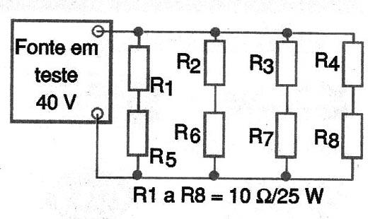
The use of resistors bank has several disadvantages. One is that we need to have a resistor to each current value we want to simulate, and this value also depends on the voltage that the tested circuit applies.
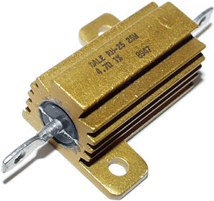
The second is the power dissipation that requires wire resistors with large dissipation, which leads us to the expensive components, not always easy to find. In Figure 2 we show a resistor such.
A much better solution and more "professional" is to mount an electronic load with a virtual resistor whose resistance can be adjusted electronically to drain the power test that the project requires.
The idea is precisely given in this article with the use of a power MOSFET which functions as a variable resistor for the tested load.
MOSFETs with currents up to 10 A and capable of operating at voltages in a typical range of 1.5 V to 50 V are common and can be found easily at a very affordable cost.
The advantage lies in the fact of having a single component to a wide range of simulated load resistors, mounted on a single sink and used easily.
The present circuit shown in Figure 3, uses a type CA3140 operational amplifier (FET) feeding a power MOSFET which can be, e.g., IRF540, or equivalent (must be mounted on the heat sink).

A load sensorresistor, the single power resistor in circuit, senses the load current sending a reference voltage for the operational amplifier, applied to pin 2.
The current then depends on this reference then being adjusted in a pot fairly precisely.
The circuit has two current ranges which are selected by a key. In the first position we have a higher operating voltage, thus making it possible to obtain higher currents in the range from 0 to 10 A, for example.
Second, we have a lower application voltage, thereby yielding one low current range between 0 and 1 with the indicated values.
The adjustment of these ranges can be made with the use of an ammeter or a voltmeter (which is more secure) connected in parallel with the power resistor R7. In this case, we remember that 100 mV measured, corresponding to 1 A.
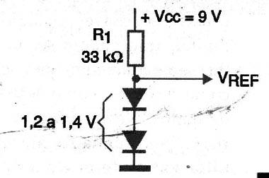
The operational amplifier of the sector and the reference voltage must be powered by separate power of 9 V, a zener diode having 1.2 to 1.6 V to obtain greater precision in the load setting.
In the absence of a precision zener diode for this function can be used two common silicon diode polarized directly, as shown in Figure 4.
The main circuit can be mounted on a small printed circuit board as shown in Figure 5, and the power MOSFET installed in a good heat sink.
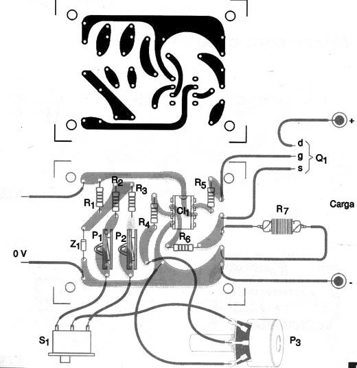
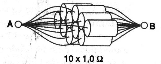
The power resistor must also be installed outside the board. In the difficulty to obtain a resistor of 0.1 Ω to 25 W connect in parallel 10 ohm resistors 1 or 3 x 2.5 W as shown in Figure 6.
Remember that draining high currents, both the power MOSFET and the resistor are heated, so these components should preferably be mounted outside the box.
Use equivalent to the MOSFET carefully check the maximum voltage and maximum current operation of this component.
Also remember that this load is indicated only for DC circuits.
CI-1 - CA3140 - operational amplifier
Q1 - IRF540 or equivalent - Power MOSFET
Z1 - 1.2V - zener diode - see text
R1 - 33 k ohm 1/8 x W - resistor
R2 - 4.7 k ohm 1/8 x W - resistor
R3 - 220 K ohm 1/8 x W - resistor
R4, R5. R6 - 1.2 k ohm 1/8 x W - resistor
R7 - 0.1 Ω x 25 W - wire resistor - see text
P1 - 4.7 k Ω - trimpot
P2 - 220 k Ω - trimpot
P3 - 47 k Ω - linear potentiometer
Miscellaneous:
Printed circuit board, heatsink for the power mosfet, battery connector and battery wires, weld, etc.


