

It is not enough to turn on the coil of a relay to the signal source so that it responds docile and quickly closing its contacts.
First we have to know if the signal being applied to its coil is really what it needs to operate and, secondly, we need to know if the current that will be controlled by its contacts are within its capabilities.
A relay is an electromechanical switch, i.e. a device which closes a pair or more of contacts from the action of the magnetic field caused by current flowing through a coil.
In Figure 1 we have represented, in a simplified manner, a relay with a pair of contacts only, which can have the position NO (normally opened) and NC (normally closed).
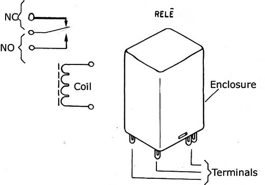
When the current flows through the coil, a magnetic field is created which draws the armature, thereby moving the contacts so that they act on the load circuit.
For the relay action to occur it is necessary that the current flowing through the coil has a minimum intensity. This intensity is also given by the voltage applied between its ends by the simple application of Ohm's law.
Dividing the voltage by the coil resistance we have the circulating current.
Well, in many applications, the simple connection of the relay to the circuit can not lead us to the expected results for several reasons. One of these reasons would be the circuit own inability to maintain tension able to provide the current that causes its triggering.
In other cases, the own available type of signal does not correspond to the one which would take the relay to a continuous operation.
Considering these cases, in applications of both radio control and other areas, we show some interesting circuits to use in small relay triggering.
PRACTICAL CIRCUITS
We begin with the simplest configuration shown in Figure 2, which is used when the current available for the firing is insufficient to actuate the relay.
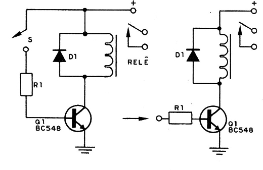
In this case, we use a transistor as a driver, capable of multiplying the current substantially to obtain a value that triggers the relay.
The transistor collector current must be greater than the one required by the relay.
Thus, transistors like BC548 can be used to trigger relays of up to 200 mA.
The value of R1 in the circuit depends on the desired amplification. On an approximate mode we can calculate this resistor as shown:
We subtract 0.6V from the circuit supply voltage, which must be equal to that required by the relay for triggering. We call this result (1).
V1 = V - 0.6 (1)
Then we divide the current required to trigger the relay by the minimum gain we assume to have the used transistor. In the case of BC548 we can secure it by 125.
We call this result of (2).
Ib = l / 125 (2)
To find the value of the resistor R1, we complete dividing the value found in (1) by the value found in (2).
R1 = V1 / b
We can only anticipate that for a relay of 100 mA, with this circuit will be enough a current of 1 mA to make its triggering.
In Figure 3 we have another interesting application with two transistors, which is an inverting stage.
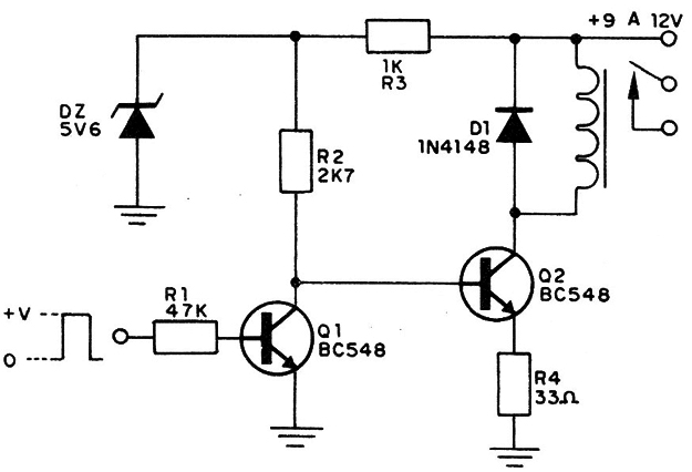
This circuit is used when we want the relay to trigger in the absence of an input signal. In short, when we apply the signal to Q1 the relay turns off.
The transistors used may be the BC547 or BC548, if the relay has an operation current up to 100 mA (we reduce the value in half of the maximum supported in theory, to avoid its overloading).
The zener diode stabilizes the operation of the circuit and it has 5.6 V x 400 mW.
In Figure 4 we have a great sensitivity circuit which allows the control of a relay from a signal of 6 V with only 1mA of current available.
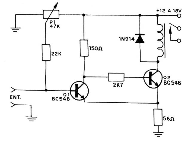
The maximum sensitivity is determined by the potentiometer set point in the relay trigger limit. This relay should have a coil current up to 100 mA with operating voltage a little lower than the supply voltage.
The diode connected in parallel to the relay coil has the purpose of protecting the transistor, because the opening and closing of the contacts occur pulses of very high voltages which could easily damage the component.
The resistor of the emitters of the transistors must have its value found experimentally for better circuit performance.
We can consider this configuration as a Schmitt Trigger, that is, a fast switching circuit when the voltage reaches a certain value.
We finally get to the circuit of Figure 5, which is a bistable multivibrator to control the relay. Its powering is done with a voltage of 12 V and its operation can be analyzed as follows:
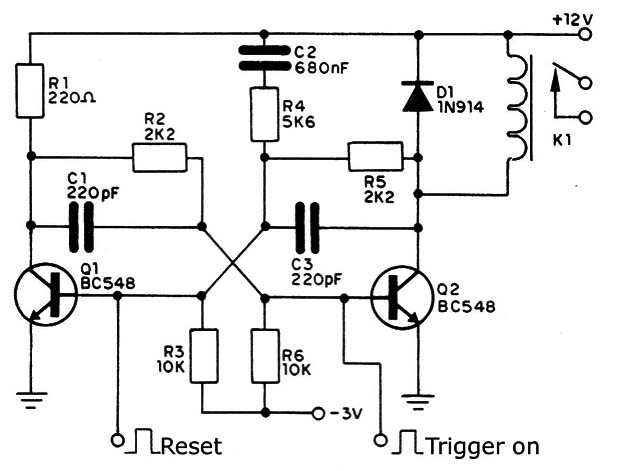
The pulse applied to the base of the first transistor, leading it to conduct triggering the circuit, deactivating the relay. This pulse must have a positive polarity and intensity according to the sensitivity of the transistor, necessary relay triggering.
To activate the relay, the pulse is applied to the other input, causing the transistor Q2 to conduct.
The minimum duration of the pulses that lead to switching is given by the feedback capacitors.


