Note: This project was published by Popular Electronics (1999).
In these times it's not unusual to see people listening to personal radios. cassettes, MP3 or even CD players through a set of headphones while walking, or while riding on buses or trains.
Those devices are just fine for the individual.
But what about those times when you find yourself traveling with a companion with whom you’d like to share a particularly memorable cut from a tape or CD, or a song on the radio?
Of course, you could plug a dualheadphone adapter into your audio device, allowing you to connect two headphones.
At first glance taking that route might seem the ideal solution, but there is an unforeseen downside.
Such adapters simply (as shown in Fig. 1A) tie the two sets of head-phones in parallel.
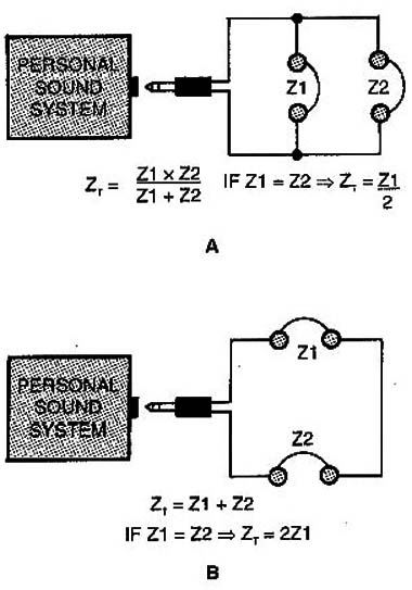
That reduces by half the total impedance seen by the output driver of your personal sound system and places unnecessary strain on the sound system’s output circuits.
And that, in turn, could lead to overheating and other problems that could possibly cause irreversible damage.
Even if connecting the adapter and a second headphone doesn’t completely destroy the unit's output driver, the loading effect is sure to severely distort the output audio to a point where it's almost unintelligible.
Alternatively, if the two headphones are series connected to the personal sound system (as shown in Fig. 1B) the increased (doubled) impedance produces power losses and could possibly severely dislort the output signal.
Ener The Sound Partner –a small low-power audio amplifier designed To provide sufficient output current to drive a second set of headphones without distorting The ooutput audio or loading the unit’s output driver.
The Sound ParTner, based on National Semiconductor's LM386 low-power audio amplifier and powered from 4 AA-cell baTTeries (i.e. a 6-voIt source), can ooutput up To 100 mW.
A Little Background. The Sound ParTner. as shown in Fig. 2 Is extremely easy to use.
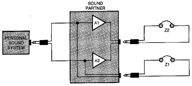
You simply connect it to the headphone jack of your personal sound system and Then connect Two headphones to the Sound Partner.
Note from Fig. 2 that audio from the personal sound system is fed to the input of the Sound Partner where the signal is split into distinct and separate left and right channel signals that divide along two paths. In the first path (going to the first set of head-phones) the unaffected signal is applied to Z1.
In the second path, the left and right channel audio is applied to a pair of low-power amplifiers.
Because the two amplifiers have a very high impedance, the Sound Partner offers no loading to the personal sound system.
How It Works. A schematic diagram of the Sound Partner is shown in Fig. 3.
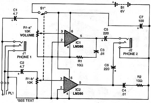
The circuit, built around a pair of low-cost LM386 low-power audio amplifiers (lC1 and lC2), can be used with common headphones with impedances ranging from To to 100 Ω.
The audio from the portable sound system is routed though PL1 (stereo phone plug) to the Sound Partner, where the stereo signal is broken down into its left and right channel components.
The stereo (the left and right channel) audio is AC coupled through a pair of 4.7-uF capacitors (C1 and C2) to VOLUME CONTROL R1 (10k dual-ganged audio-taper potentiometer with a piggy-backed SPDT switch S1).
Capacitors Cl and C2 are used to prevent any DC from reaching the circuit.
After signal level adjustsignals are fed to a pair of LM386 amplifiers, where the signal is ramped up to a level sufficient to drive a set of stereo headphones.
The amplified outputs of IC1 and lC2 are routed through C5 and C6, respectively, to jack J2 and applied to the connected headphones.
Power for the Sound Partner is provided by a 6-volt power source B1 (comprised of 4 AA-cell batteries).
The source voltage is filtered by C7, a 100 µF electrolytic capacitor to establish a relatively ripple-free power source for the Sound Partner.
Construction. There is nothing critical about the construction of the Sound Partner, so the circuit can be put together using any assembly method with which you are comfortable.
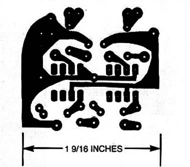
The author's prototype of the circuit was assembled on a printed-circuit hoard measuring 1 by 1.7 inches.
A full-size template of the author’s printed-circuit layout is shown in Fig. 4.
Once you’ve obtained all of the components listed in the Parts List, construction can begin.
If you intend to build the circuit on perfboard, using point-to-point wiring techniques, assemble the circuit using the schematic diagram (Fig. 3) as a guide.
If you take a non-printed-circuit approach to assembling the circuit, be sure to pay strict attention to the electrical orientation of the polarized components.
For those who prefer the printed-circuit approach, assemble the Sound Partner's printed-circuit board guided by the parts-placement diagram shown in Fig. 5.
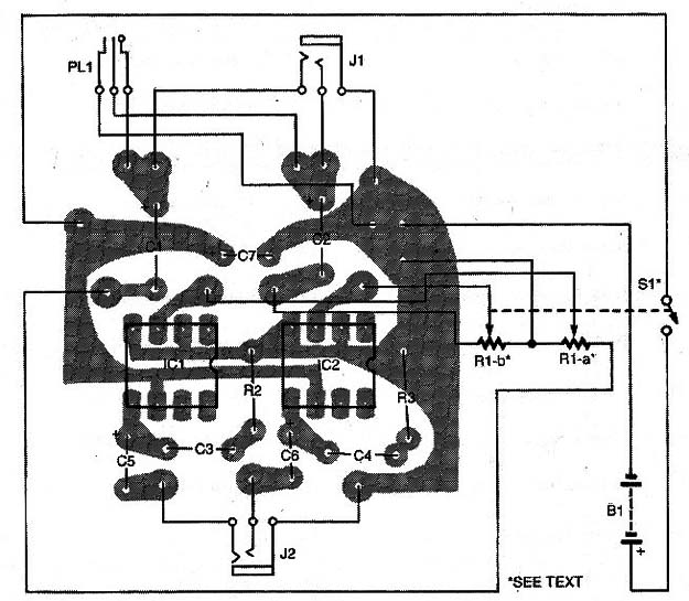
Note that with the exception of the input and outputjacks, the batteries and battery holder, and the VOLUME control (Ri), all of the components mount to the printed-circuit board.
The off-board components can be wired to the rest of the circuit using 22- or 24-gauge stranded wire.
Note: If desired, separate components can be used in place'of R1 -a, R1 -b, and S1.
Once completed, the circuit can be housed in any plastic or other non-metallic enclosure, with the printed-circuit board fixed in position using a few (2 or 3) machine screws with nuts and washers.
If the board is housed in a metallic enclosure, It is wise to mount the board on quarter-inch spacers to prevent shorting.
Prior to mounting the circuit board and off-board assembly into its enclosure. carefully drill holes at convenient locations in the enclosure wall(s) to ccommodate the off-board components S1, J1, J.2, B1 (along with its 4 AA-cell battery holder), and R1 (the VOLUME control).
Be careful when drilling holes in a plastic enclosure: Too much pressure can cause the plastic to crack.
Testing. Once the circuit has been completely assembled check your work for the usual construction errors-solder bridges, misoriented or mispositioned (e,g., improperly located) components, etc.
When you are satisfied that the circuit contains no construction errors, it is time to test the project.
Note: No calibration adjustments are needed. Simply plug PLi into the headphone output of the personal sound system and connect two to 100-ohm stereo headphones to the Sound Partner outputs (J1 and J2). Set power switch Si (ganged to R1) to the off position, install the batteries in their holder, and the Sound Partner is ready for use.
Adjust the audio level for headphone 1 (J1) using the volume control of the personal-sound system.
After that, adjust volume of headphone 2 by adjusting R1.
Caution: Never use the Sound Partner without a headphone connected to J1.
Doing so could damage your personal sound system.
When all is working properly, there is nothing left to do but seal the project into its enclosure plug it into your personal sound system, and share that must-hear tune.
RESISTOR
(All fixed resistors are ¼ watt, 10% units)
R1 – 10.000 Ω dual-gang, audio taper potentiometer with SPST switch (see text)
R2, R3 – 10 Ω
CAPACITOR
C1, C2 – 4.7 µF 16-WVDC, miniature electrolytic
C3, C4 = 0.01 µF, ceramic-disc or metal film
C5, C6 – 220 µF , 16 WVDC, miniature electrolytic
C7 – 100 µF, 16 WVDC, miniature
Additional parts and materials
IC1,IC2 – LM386 lower audio-amplifier, integrated circuit
B1 – 6-volts battery, see text
J1, J2 – 1/8 inch stereo jack (see text)
PL1 – 1/8 inch stereo phone plug (see text)
S1 – SPST (ganged R1)
Printed-circuito materials, 8-to 100-ohm headphones, plastic knob, enclosure, battery holder, IC sockets, wires, solder, hardware, etc.


