

Note: this article was originally published in the Poptronics magazin year 2000.
Picture this: You have a radio or amplifier on the bench that has no output.
Obviously, trying to find the “break in the chain” where the signal stops on its trip from input to output can be frustrating and time-consumlng without the right test equipment.
The best way to find the bad component is to start checking in those parts of the circuit where you know the trouble is.
So how exactly do you do that? By injecting a known signal into the circuit and tracing Its path, you can quickly and easily find the point where it disappears.
You can use an oscilloscope and a signal generator, but what if you don’t have ready access to those items?
That’s where the AF/RF Signal Chaser presented here comes to the rescue.
With care and proper construction techniques, this low-cost project can fit on a piece of perf-board small enough to fit in a shirt pocket.
Powered by a 9-volt battery it can be used “in the field” as well as on the bench if a piece of equipment can be easily diagnosed and fixed where it stands you won't have to drag It back to your bench.
The AF/RF Signal Chaser is useful for finding problems in AM and FM radios, CD players, common amplifiers, multimedia audio systems, and televisions.
However, electronics hobbyists and technicians aren't the only ones who can make use of this proiect: there are many more non-obvious applications for the AF/RF Chaser.
For example, the amateur scientist or the high school or college student looking for a different type of science project can use this circuit as a light-to-sound converter or a sound- and RF-‘sniffer" to perform some interesting experiments involving physics, chemistry, natural sciences-to name a few.
By connecting a coil to the input, you can pick up audio and RF signals inductively from transformers or low- power transmitters.
To use the AF/RF Signal Chaser as a light-to-sound converier connect a photocell to its input instead of the coil mentioned above.
Now you can listen to lightbulbs, the sun, stars, or any other modulated light source, whether visible or not.
How It Works.
Any signal detector like the AF/RF Signal Chaser needs the ability to work with weak low-level signals: some form of amplification ls required.
To that end, we'll be using National Semlconductor’s LM386 low~voltage audio amplifier.
Originally designed for small radios with headphones or small loud-speakers, the LM386 is a complete audio amplifier in an 8-pin dual-ln-llne package.
Features that we will be taking advantage of include a very low quiescent current (4 mA) a wide supply-voltage range (4 to 12 volts), and the ability to drive 8-ohm speakers at up to 325 mW on a 9-volt supply.
What’s more, those features are designed so that few external components are needed.
The LM386’s pinout is shown in Fig. 1A.
. Its basic circuit is very simple, requiring few external parts to drive an 8-ohm speaker (B).")
Figure 1B shows a typical application circuit for the use of an LM386 as an audio amplifier.
Note that connecting a capacitor to pins 1 and 8 sets the output galn.
Wilh a 10 µF capacitor the voltage galn is 200. You can see the effect of the gain capacitor in the response chart of Fig. 2.

If you need more from the LM386, simply boost the supply voltage.
The relationship between output power and supply voltage can be seen in Fig. 3.

Another feature In signal-tracing that is very important to performance is the input impedance.
Unfortunately, the LM386 has an input reslstance of only 50,000 Ω.
Any high-impedance circuit that we try to test will be loaded down and stop working; it will see the AF/RF Signal Chaser as a short circuit.
What we need to do is increase the circuit's input impedance to the point that it will be undetectable by whatever circuit we’re testlng.
To do that, we’ll use a field-effect transistor as an input buffer.
Those devices can have very high input lmpedances; the one we’ll be using is rated at about lo megΩ.
That amount of loading (or lack thereof) should be good for the majority of circuits that we’ll be testing.
Circuit Description.
The schematic diagram for the AF/RF Signal Chaser is shown in Fig. 4.

The signal from J1 is amplified by Q1 with R1 and R2 providing a bias for the FET.
The amplified signal is capacitively coupled to R4 (volume control) and D1.
The purpose of D1 is to act as a demodulator for RF signals.
If you're working with audio signals find D1has no effect on the signal.
On the other hand, when working with RF signals the diode acts like an old- style crystal-set demodulator.
The inclusion of D1 gives the AF/RF Signal Chaser its versatility.
Both frequency-modulated (FM) and phasemodulated (PM) signals can be detected; D1 acts as a slope detector.
However, the audio will be poor in fidelity.
The remainder of the circuit is a standard LM386 amplifier with a galn of 200 and an 8-ohm output.
Any suitable speaker or earphone can be connected to J2.
Note that R1 and R4 are coupled so that the AF/RF Signal Chaser’s volume control also turns it on and off like a battery-powered radio.
The power supply is a set of four AA batteries in an appropriate holder.
Construction.
In spite of its sensitivity, the AF/RF Signal Chaser can be built on a piece of perfboard using standard construction techniques, the method used in the author's prototype.
If you'd like to use a PC board, you’ll have to design one yourself.
Vifith the exception of J1, J2, B1.and the R4/S1 combination, all components mount on the perfboard.
If you like, you can use a small piece of universal printed-circuit board that matches modular breadboard sockets with predrilled connecfion points.
Keep the connections as short as possible.
When you are finished wiring the board, check your work against Fig. 4 for any wiring mistakes or wrong components.
Use solid bus wire for any short jumpers that you might need; use insulated wires for the longer runs. Stranded 22-gauge wire connects the external components, such as the jacks, battery, and volume control, to the board.
It is advisable to use a plastic or other non-metallic box to house the project.
Many small plastic boxes can be found at electronics stores like RadioShack or many mail-order firms; choose one that can hold all of the components.
Drill appropriate holes for the board, jacks, volume control, and battery case.
Be careful when drilling holes in plastic boxes-too much pressure can crack the plastic.
In addition, plastic has a tendency to “kick up” during drilling; be sure to hold it firmly.
An alternate method for making holes in a plastic box is with the sharp point of a hot soldering iron.
Melt the tip through the plastic and make circular motions to enlarge the hole to the needed size.
Be careful not to apply too much heat.
This method should only be done in a well-ventilated area-outdoors if possible.
The fumes that the melting plastic might give off can be harmful.
Don’t forget to clean the soldering iron’s point after the “drilling” operation standard construction techniques- the method used in the author's prototype.

Mount the PC board with two or three machine screws, nuts, and washers. You may use coupling nuts to act as spacers to hold the board away from the case.
You can put additional input connections in parallel with J1.
One suggestion is a pair of wires with an alligator clip on the ground wire and a meter probe on the other.
You can also build that as an “accessory” terminated with a ½ inch phone plug.
That way, you can plug in the probe attachment when needed instead of having it dangle from the unit all the time.
While we suggest a 1-inch jack for J2, you should choose an appropriate jack to match the type of plug on your speaker wire or ear-phone.
lf you are using stereo headphones, J2 should be a stereo jack.
Although the obvious choice would be to wire the two stereo channels in parallel, it’s better to wire them in series.
That way, the headphone impedanoe is higher and reduces current drain on the battery.
An option that you might want to consider is an LED “power-on” indicator.
Simply wire a 1.000-ohm resistor and an LED across C6; the details are shown in Fig. 5.

lf you’re satisfied with your work snap a set of four fresh AA batteries into the holder and close up the case; the AF/RF Signal Chaser is ready for use.
Using the AF/RF Signal Chaser.
No adjustments are needed.
Plug an appropriate probe (such as the two-wire arrangement we mentioned before) into J1 and a set of head-phones into J2.
Clip the ground wire to circuit ground near the point of the circuit that you’re testing (a radio, for example), turn R4 to a comfortable listening level, and probe away!
To learn how to use the AF/RF Signal Chaser, you should look at the schematic diagram (Fig. 6): it shows some test points in a common portable transistor radio.
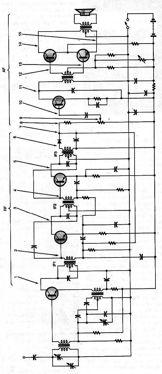
Simply start at the front end and work your way through the circuit to the output.
The high input impedance of the AF/RF Signal Chaser means high sensitivity which allows some unusual applications, including the suggestions at the beginning of this article.
Here are more with a few details on how to do them:
Connect a coil to J1 for an inductive pickup. You can listen to the audio transformers in audio amplifiers or to the IF transformers in AM/FM receivers. The coil is either an audio transformer‘s primary winding without The core or a Telephone pick-up coil. You can also use the circuit to get the signal from or telephone.
Conneci a photocell or phototransisor to the input and you can listen to lighT bulbs, fluorescent lamps, TV screens computers screens, etc. That simple exercise can grow inTo an involved program of scientific experiments in convening light to sound.
Connect a 200 To 500 ohm ceramic or crystal microphone to.J1. The resull: a sensitive elecironic stetosscope. You will be able to hear the sounds of leaking plumbing or animal sounds-including the chomping of termites.
Use a piezo-ceramic disc protected against water to hear the sounds of marine life
Place a microphone connecied to J1 in the center (focus) of a parabolic reflector. You can hear birds and other wildlife from a distance without disturbing them.
Once you start experimenting with the AF/RF Signal Chaser, you’ll never look at it again as “just another piece of test equipment ".
THE AF/RF SIGNAL CHASER SEMICONDUCTORS
IC1 - LM386 low-voltage audio power amplifier, integrated circuit
Q1 - MPFl 02 N-channel junction field-effect transistor
D1-1N34 germanium signal diode
RESISTORS
(All resistors are 1/8-watt, 10% units unless otherwise noted.)
R2l -220,000-ohm
R2 - 10,000,000-ohm
R3 - 3300-ohm
R4- 10 k ohm panel- mount potentiometer with integral single-pole double-throw switch
R5 - 10-ohm
Capacitors
C1 – 0,022 µF – ceramic
C2 – 0,1 µF –ceramic
C3 – 10 µF – electrolytic
C4 – 0,05 µF – ceramic
C5 – 220 µF – electrolytic
C6 – 100 µF – electrolytic
Additional Parts and Materials
B1 – 6-volt battery – 4 Aacells
J1 – 1/8 inch phone jack
J2 – 1/8 inch phone jack
S1 – Single pole double throw switch )part of R4)
8 to 64 ohm earphones


