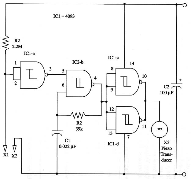
Note: this circuit was published in a Brazilian magazine by the author and them translated into English to be part of one of his books.
The device can be powered from 6 to 12 V power supplies, and current drain is very low-only 0.5 mA when the sound is off.
A schematic diagram of the water sensor is shown in Fig. 1.

The sensor is made with two bare wires that touch the water, thereby triggering the circuit on.
This sensor should be positioned at the level at which the reader wants the alarm to sound. X3 is a piezoelectric transducer or a crystal earpiece, but if you want a higher audio level, use a transistorized output stage to drive a loudspeaker, as shown in other projects in this section.
The frequency of the audio tone is determined by R2 and C1.
You can alter this frequency by changing the value of R2.
This resistor can assume values between 22 and 100 k Ω.
For an adjustable tone, replace R2 with a 100 k Ω potentiometer and a 10 k Ω series resistor.
Wires to the sensor can be long. The power supply is formed by four AA cells, a 9 V battery, or an ac-to-dc converter.
Don’t use a transformerless supply in this project!
IC1 - 4093 CMOS integrated circuit
X1, X2 - Water sensor (see text)
X3 - Piezoelectric transducer or crystal earpiece
R1 - 2,200,000 Ω, 1/4 W, 5% resistor
R2 - 39,000 Ω, 1/4 W, 5% resistor
C1 - 0.022 µF - ceramic or metal film capacitor
C2 -100 µF, 16 WVDC electrolytic capacitor


