

Small pieces of optical fibers can be obtained relatively easily from several sources such as, manufacturer samples, decorative lamps and other places (at the electronics fairs in São Paulo - Brazil, an optical fiber manufacturer distributed a huge amount of optical fiber pieces to visitors and which could be used in this assembly).
If the reader has a small piece of optical fiber similar to the assembly of this device it will not be very difficult. If the reader works with communications surely getting a piece of optical fiber of a few centimeters will not be an obstacle to the realization of this project.
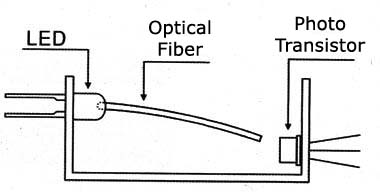
The basic idea of the project is to critically focus a light beam through an optical fiber so that it covers a photo sensor.
As the fiber is suspended only attached by one end, any swing can take it from its position causing the sensor from receiving the light and thereby triggering a timer circuit. In Figure 1 we give an idea of ??how this can be done.
As the emitter (fiber and LED) and the receiver can stay away from the trigger circuit, the sensor or alarm can be used in many practical applications involving the protection of objects and places or monitoring the operation of industrial equipment and others.
Of course, with demonstrative purpose all the elements can be assembled on the same site instead of the relay we can use a small buzzer or an audio oscillator as an output.
In Figure 2 we show how this can be done.
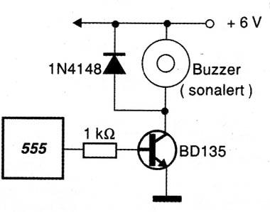
The oscillator tone given as an example is set by a trimpot.
HOW IT WORKS
The LED1 is the light source that is coupled to a small piece of optical fiber. The optical fiber is fitted in a small hole drilled in the plastic casing of the LED itself and secured with a drop of strong glue in such a way that the light radiation appears at its other end.
Positioned so that the free end aligns with a phototransistor, the fiber keeps this illuminated sensor and therefore in conduction.
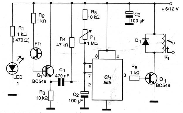
The phototransistor emitter current is applied to the base of a second transistor (Q1) so as to keep it in conduction and therefore the pin 2 of the integrated circuit 555 at a high level.
Accordingly, the integrated circuit, which is configured as a monostable multivibrator remains disabled.
When a small vibration causes the optical fiber to oscillate the focused light ceases to reach the sensor and thus the phototransistor will shear.
The result is that Q1 has its emitter current reduced enough to take pin 2 of the integrated circuit to the low level because the voltage drops and therefore its triggering occurs.
With the trigger, the output of the integrated circuit 555 goes to a high level for a time interval that depends on both the P1 set as the value of the capacitor C1.
With the values of the components listed, this time can reach up to two minutes. However, if the reader wants longer shooting intervals we can increase the capacitor C1. The maximum recommended value of this capacitor is around 1 500 µF, since higher values represent scapes which can unsettle the operation of the circuit.
At the output of the 555 we have a transistor that when in conduction, drives the coil of a small relay. This relay, depending on the characteristics of its contacts, can trigger warning systems of great power.
The circuit is powered by a voltage of 6V can be provided by a power supply or a battery.
As this battery should keep the LED lit, which means a current between 20 and 50 mA, according to the value of R4 and the sensitivity of the sensor, in applications where the system should stay very long on it is not recommended the use of batteries but the use of a power supply.
This supply should have a voltage according to the used relay and a current in the range of 200 to 500 mA. It is recommended the use of a stabilized source.
However, in demonstrations, when the circuit is turned on for a short time, small or medium batteries may be used.
ASSEMBLY
In Figure 3 we have the complete diagram of the alarm.
The arrangement of the components on a printed circuit board is shown in Figure 4.
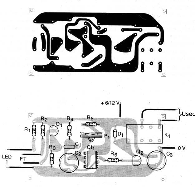
The resistors are all 1/8 W or greater and the capacitors must have a minimum working voltage of 6 V. The trimpot may be replaced by a potentiometer on the experimental setup, in order to achieve the variation of the trigger time.
The resistor R3 can be altered in the range of 10 k Ω to 100 k Ω for greater sensitivity, if there are difficulties on the focusing of the fiber in the phototransistor.
Any phototransistor may be used, including the Darlington types that provide greater sensitivity.
The relay may be any type of low cost with the coil voltage of 6 or 12 V and maximum current at 50 mA, and if the base has a different format from the original, changes in the design of the printed circuit board should be made.
The critical point of the assembly is the sensor.
In the red round common LED the reader must carefully make one small hole with a drill of 1 mm thickness. This hole should penetrate just enough to allow the fitting of the fiber, it can not in any way reach the emitter semiconductor chip, as shown in Figure 5. If this happens the LED will be damaged and no longer functioning.
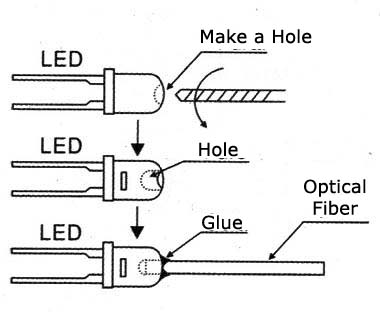
After the fiber is fitted it can be held in place with a drop of any strong glue (Super Bond, for example).
After coupling the LED to the fiber it will be interesting to power the LED with 6 V and a resistor of 470 Ω in series and check if the emitted light appears on the fiber end. Note that R1 in series with the LED should be of 470 Ω if the power is done with 6 V and 1 k Ω if the power is done with 12 V.
Both the LED and the phototransistor are kept in a printed circuit board. The LED should be positioned so that the fiber has its extremity aligned with the phototransistor as shown in the Figure 5.
It will be interesting to assemble this system protected from the ambient light in order to avoid that it falls on the photo-sensor and thereby causing a sensitivity loss to the circuit.
TEST AND USE
For testing we should just turn on the circuit and initially put the trimpot P1 in the least resistance position. The fiber must be aligned with the photo-sensor.
There may be the relay trigger when the power is established, but a few seconds later, the light reaching the photo sensor, the relay must turn off.
Lightly moving the fiber or swinging the sensor, the circuit should trigger.
If not, change the value of R3. If you want you may use a trimpot of 1 M ohm in the place of this component to obtain a sensitivity adjustment.
Proven it works, you should only make the final installation of the sensor in the location where you want to detect any swing.
If the sensor has a part of fiber unprotected it also becomes sensitive to small air currents and the system can be used to detect "wind".
For using it in industrial machinery you should simply build the sensor in the location where you want to detect the vibration.
The length of the fiber determines the amplitude of the vibrations which can be detected. Depending on the application the fibers can have its length altered. It will be convenient to experiment in order to get the optimal length for the target application.
Another interesting possibility is to connect two phototransistors in series in order to give us an optical gate. With two fibers attached to these phototransistors we will have the system activation only when vibrations in two places or in two modes are detected.
If one of the sensors is in a vertical position and at the other one in the horizontal, for example, we will have a configuration which only detects combined vibrations.
Semiconductors:
FT1 - Phototransistor - See text
CI-1 - 555 - Integrated circuit
Q1, Q2 - BC548 or equivalent - NPN transistor for general purpose
LED1 - Common red LED - See text
D1 - 1N4148 - General purpose silicon diode
Resistors: (1/8 W, 5%)
R1 – 1k ohm (12 V) or 470 ohm (6 V) – see text
R2, R6 – 1 k ohm
R3 – 10 k ohm
R4 – 47 k ohm
R5 – 10 k ohm
P1 – 1 M ohm – potentiometer
Capacitors:
C1 – 470 nF – ceramic or polyester
C2, C3 – 100 µF x 16 V – electrolytic
Other:
F.O. – Optical fiber
K1 – 6 or 12 V relay – 50 mA to 100 mA
S1 – SPST switch
B1 – 6 V – 4 AA cells
Printed circuit board, a box for the assembly, a battery holder or power supply, wires, welding, etc.


