Note: this article is parft of one of my books. More about transistor can be found in other articles in this site.
How They Are Made
Bipolar transistor can be found in two basic structures shown by figure 1.
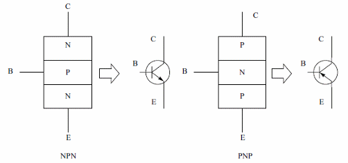
They are formed by three pieces of semiconductor materiais (generally silicon), forming two junctions in the some crystal. Altough the structure can be compared with two diodes placed back-to-back, the fact that they are in the same crystal means the events occuring at one junction can influence those at the other.
The possibility of control makes the transistor an important element in mechatronics applications. According to the type of semiconductor, the strucutures result in two types of transistors - NPN and PNP.
Observe in the figure that to each piece of semiconductor material, terminals or leads are placed corresponding to the three regions: base (B), emitter (E) and collector (C).
2 - How they Work
As shown by figure 2 a current flowing between emitter and collector can be controlled by a current flowing through the base.
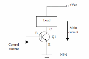
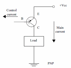
The direction of the currents depends on the type of the transistor. The currents in NPN transistor flow in opposite direction than in PNP transistors, as shown by figure 3
But the important to consider in the transistor action is that a small current flowing between the base an the emitter can control a large current between collector and emitter.
This means that the transistor has a "gain" or "amplification factor" (also called Beta). If a current of 1 mA through the base causes a 100 mA current through the collector, the transistor has a "beta" of 100.
The transistor can be used in two different ways according the "characteristic curve" shown by figure 4.
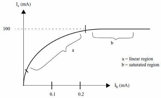
When operating in the linear region, small changes in the base current will cause large changes in the collector current. In this type of operation the transistor acts as a signal amplifier. If the base current is an audio signal, this signal will appear amplified in the collector.
When operating in the saturation region, the transistor acts as a switch. A current in the base "turns-on" the transistor leting a large current flow to the collector, as shown by figure 5.
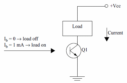
The use of the transistor as swith is the most important in mechatronics, since this element can be used to control large loads as motors, solenoids, SMAs, relays and others from small currents.
Many articles showing how to use transistor as drivers for solenoids, relays, motors and other loads can be found in this site.
Specifications
Based on the applications it is possible to find transistors of different sizes and formats with gains ranging from 5 to 1000. The transistors are also classified according the amount of current they can handle.
Small transistors, signal transistors or general purpose transistors can control only small amounts of currents. They are intended to applications where low signal may be amplified or controlled. Typical types can't control currents above few hundreds milliamperes.
An important type of transistor is the "Power Transistor" that can control large currents as the ones drained by motors, solenoids, SMAs and other loads found in mechatronics designs.
Figure 6 shows some types of common transistor featuring the Power Transistors with larger sizes.

The Bipolar Power Transistor generate heat when in operation and by this cause they need to be mounted on heatsinks. The size and the type of heatsinks depends on the amount of power generated by the transistor in an application.
When using a transistor we must observe the electrical, mechanic and thermal cracateristics of a determinated type as follows:
a) Maximum Voltages
Vce(max) - the maximum voltage that can be applied between collector and emitter.
Vceo(max) - the same but with open base.
Vcb(max) - The maximum voltage that can be applied between collector and base
Vcbo(max) - the same but with open emitter
Veb(max) - The maximum voltage that can be applied between emitter and base
Vebo(max) - the same but with open collector.
b) IC(max)
Is the maximum current that can flow through the collector terminal. Other currents as Ib, Ie can also be indicated.
c) Gain
A small current forced to flow by the base causes a large current to flow between emitter and collector. The number of times the collector current is larger than the base current is the gain of a transistor or Beta factor (?), The gain can also be indicated by a hybrid parameter named hFE.
d) Pd(max)
When conducing a current the transistor generates heat that must be transferred to the air. The maximum amount of heat produced by a transistor is given by its maximum dissipation power or Pd(max).
e) Transition Frequency - fT
The gain of a transistor falls when working with high speed signals. There is a frequency where the gain falls to unit. It is named transition frequency or fT. This means that in this frequency a variation of 1 mA en base current causes a variation of 1 mA in the collector current and the transistor cannot operate as an amplifier.
Formula:
Power generated by a transistor:
Pd = Vce x I
Where:
Pd is the power nproduced (and dissipated) by a transistor (W)
Vce is the voltage between emitter and collector when the transistor is conducing (V)
I is the current flowing through the transistor (A)
Obs: common bipolar silicon transistor have typical Vce when conducing (saturated) between 1.2 and 2.5 V.
Formula:
Gain of a transistor:
hFE = Ic/Ib
Where:
hFE is the gain (beta)
Ic is the collector current (mA)
Ib is the base current that causes the collector current (mA)
Transistor Identification Codes
The three standard transistor marking schemes are:
1.Joint Electron Device Engineering Council (JEDEC).
These take the form: digit, letter, serial number, [suffix]
The letter is always 'N', and the first digit is one less than the number of legs, (2 for transistors except for field effect transistors – FETs – that use the 3N and except for 4N and 5N which are reserved for optocouplers. The serial number runs from 100 to 9999 and tell nothing about the transistor except its approximate time of introduction.
The (optional) suffix indicates the gain (hfe) group of the device:
A = low gain
B = medium gain
C = high gain
No suffix = ungrouped (any gain).
See the data sheet for the actual gain spread and groupings. The reason for gain grouping is that the low gain devices are cheaper than the high gain devices, resulting in savings for high volume users.
Examples- 2N3821, 2N2222A, 2N2904.
2.Japanese Industrial Standard (JIS).
These take the form: digit, two letters, serial number, [suffix]
Again, the digit is one less than the number of legs.
The letters indicate the application area and flavor of the device according to the following code:
SA: PNP HF transistor
SB: PNP AF transistor
SC: NPN HF transistor
SD: NPN AF transistor
SE: Diodes
SF: Thyristors
SG: Gunn devices
SH: UJT
SJ: P-channel FET/MOSFET
SK: N-channel FET/MOSFET
SM: Triac
SQ: LED
SR: Rectifier
SS: Signal diodes
ST: Avalanche diodes
SV: Varicaps
SZ: Zener diodes
The serial number runs from 10-9999. The (optional) suffix indicates that the type is approved for use by various Japanese organizations.
NOTE: since the code for transistors always begins with 2S, it is sometimes omitted so, for example, a 2SC733 would be marked C 733.
Examples- 2SA1187, 2SB175, 2SC733.
3.Pro-electron.
These take the form: two letters, [letter], serial number, [suffix]
The first letter indicates the material:
A = Ge
B = Si
C = GaAs
R = compound materials.
The second letter indicates the device application:
A: Diode RF
B: Variac
C: transistor, AF, small signal
D: transistor, AF, power
E: Tunnel diode
F: transistor, HF, small signal
K: Hall effect device
L: Transistor, HF, power
N: Optocoupler
P: Radiation sensitive device
Q: Radiation producing device
R: Thyristor, Low power
T: Thyristor, Power
U: Transistor, power, switching
Y: Rectifier
Z: Zener, or voltage regulator diode
The third letter indicates that the device is intended for industrial or professional rather than commercial applications. It is usually a W,X,Y or Z. The serial number runs from 100-9999. The suffix indicates the gain grouping, as for JEDEC.
Examples- BC548A, BAW68, BF494, BFY51.
Apart from JEDEC, JIS and Pro-electron, many manufacturers often introduce their own types, for commercial or other reasons. Examples of specific prefixes are:
MJ: Motorola power, metal case
MJE: Motorola power, plastic case
MPS: Motorola low power, plastic case
RCA: RCA
RCS: RCS
TIP: Texas Instruments power transistor (plastic case)
TIPL: Texas Instruments planar power transistor
ZT: Ferranti
ZTX: Ferranti
Examples- ZTX302, TIP31A, MJE3055, TIP31, TIP120.


