

Translated into English by Patricia Lima Carlos.
The traditional analogue versions that operate in Class A, B and C do not meet these requirements, and therefore Class D audio amplifiers are used in all these applications. See in this article what these amplifiers are and what the advantages are in their use.
The traditional audio amplifiers are analog circuits, amplifying voltages and applying them to transducers such as headphones and speakers, without changing their features, as shown in Figure 1.

It is relatively simple to obtain a linear amplifier circuit using traditional components such as valves, bipolar transistors or just field-effect transistors. Even a single transistor properly polarized can become a simple amplifier, driving a small speaker or headset, as shown in Figure 2.

However, this type of circuit does not meet the modern needs, mainly of the devices fed by batteries: its performance is very low. Most of the energy that is delivered to this type of circuit is converted into heat in the power components. Just note that the output transistors, even for equipment with relatively low power, need to be built in good heat sinks. By touching these heat sinks when the equipment is working can give the reader an idea of ??how much energy is lost in the form of heat.
To meet the needs of new equipment, low-power and high-performance configurations are used. It is the Class D amplifiers that, in order for the reader to better understand how it works, we will explain from the beginning comparing them to traditional amplifiers.
Class A
The simplest configuration for an amplifier is what we show in Figure 2 and which can be analyzed in a more complete way with the Figure 3 circuit.

In this configuration the transistor must be polarized by the resistor Rb so that it operates in the center of the charge line, shown in Figure 4.

This means that the transistor together with the transformer that powers the circuit form a voltage divider and there is a voltage on the transistor collector equivalent to approximately half the voltage of the power supply. Thus, when the audio signals are applied at the input of this circuit, they make the voltage applied to the transformer oscillate between a maximum close to the supply voltage and a minimum near 0 V as shown in Figure 5.

Of course, in the absence of a signal, the transistor must remain in conduction so that the voltage in its collector remains at half of the power. With this the transistor remains dissipating power in the form of heat even when there is no signal at its input.
The losses in this circuit are such that more than half of the power is dissipated in the form of heat, apart from the fact that even at rest its consumption is high. Something inadmissible for a battery-powered application.
Class B
A type of circuit that offers a gain in performance compared to the previous one and so it is still found in some economical portable applications like low-cost AM and FM radios is the one which corresponds to the Class B output stage in push-pull whose diagram is shown in Figure 6.

In this circuit, the two transistors are polarized in such a way that they are near the beginning of the conduction point or even in the cut, using for this purpose a special transformer. This transformer has a winding with a central socket in such a way that when a signal is applied to its primary the positive half-cycles polarize the transistor A so that it amplifies the signals, while the negative half-cycles polarize the transistor B in the same direction.
Thus, while a transistor A amplifies only the positive half-cycles of the signal, transistor B amplifies only the negative half-cycles. In the absence of a signal, neither transistor conducts and the circuit consumption is extremely low. In the collector of the transistors we have another transformer that is used as load which reunites the amplified signals recovering their original form which appears in its secondary, as shown in Figure 7.

Despite its good performance this circuit has some problems. The biggest one is that you need a transformer driver and an output transformer, which are problematic components in terms of cost and size, especially if we need high power.
The second point is that the transistors take some time to start conducting with the signal applied, because they only do this when the base voltage reaches 0.7 V. This introduces a certain distortion in the signal, as shown in Figure 8.

By polarizing the circuit in a way that the transistor is about to conduct, as shown in Figure 9, we can eliminate this distortion and obtain good power amplifiers and excellent sound quality.

In fact, using transformers made with special sheets (ultra linear) and valves instead of transistors (or even power MOSFETS) the crossover distortion can be reduced to negligible values, obtaining the best amplifiers in sound quality. There are groups of sound enthusiasts who say such amplifiers are irreplaceable in terms of sound quality, and purchase special equipment that cost thousands of dollars.
An "ultra linear" amplifier with AB-class push-pull output using valves with gold-coated anodes can be close to $10,000!
--Class C
In the Class C amplifiers the active elements such as, for example, transistors are polarized so that they conduct only half of the cycles of the input signals, as shown in Figure 10.

These amplifiers are used in applications that involve audio signals because of the distortion they introduce. However, with the use of appropriate output filters which eliminate the harmonics generated in the amplification process and return the original sinusoidal form of a high-frequency signal, they can be used in transmitters. In Figure 11 we show a typical output stage of a transmitter in class C.

Class D
The basic idea of the stages in class B is to work with impulses. It is, in a way, the digitization of the audio signal if we consider that the impulses are discrete quantities. Thus, for the reader to have an idea of ??how this works we will start from a simple bridge configuration using power field effect transistors which is shown in Figure 12.

Taking as an example an input audio signal which corresponds to a sinusoid we can transform it into pulses by sampling its intensity in a number of instants. Thus, by the Nyquist criterion, which is used when it comes to the digitalization of signals, we see that in order to reproduce this end faithfully we need to have a number of at least 3 samplings per signal cycle. In practice, the sampling is done at a frequency many times higher than the higher audio frequency which must be reproduced. In common circuits used in commercial devices, to retrieve the original signal with good fidelity the sampling must be done at a frequency at least 10 times higher than the higher frequency which is desired to be reproduced.
As shown in Figure 13, with a large number of samplings, we can retrieve the original signal more easily when we pass them through an appropriate filter.

We can say that what is done is to transform the signal intensity not into digital values, as in an ADC converter, but into pulses of width proportional to this intensity. The circuit is actually a PWM where the integration of the pulse widths will correspond to the signal to be reproduced.
By their intensity these pulses will saturate the output transistors so that, being on or off, they theoretically do not dissipate any power, as shown in Figure 14.

When they conduct the resistance between the drain and the source is zero and that is why the voltage is zero, and when they are open the current is null. Of course, in practice, in the short interval of time when the transistor switches, a certain power is dissipated, but it is much smaller than that of a linear amplifier. In order for the load not to directly receive pulses, which would not lead to the reproduction of the original signal, a filter circuit must be present as shown in Figure 15.

The signal is then integrated being taken to its original analog form
for reproduction, as shown in Figure 16.

In Figure 17 we have a full class D amplifier with its blocks as we find in integrated circuits used in telecommunications.

The fact that we work with sampling and then with pulses introduces a certain harmonic distortion to the signals. However, with the use of good filters, this distortion can be taken to values lower than 1%. Values of this order would hardly be noticed by the human ear. Another problem that designers have to work with when designing class D amplifiers is the residue of the high sampling frequency that can result in noise.
Class D in Practice
When it comes to a project using a Class D amplifier, we need to know what kind of audio signal we are working with. For the human voice we need a narrow range, but if we have a CD player or a sound system to be connected to a computer, the range should be wider. We need more fidelity.
Thus, in the practical applications, depending on the frequency range which we must reproduce we have the following characteristics:
| Devices | Passing Band | Sampling Frequency Range |
| Telecommunication (Cell phones, etc) | 5 kHz | 125 kHz to 1 MHz |
| Radio AM/FM | 15 kHz | 250 kHz to 1 MHz |
| Audio on a PC | 20 kHz | 250 kHz to 1 MHz |
| High-fidelity Audio | 20 kHz | 250 kHz to 500 kHz |
Note that the filter design is directly connected to the sampling frequency. Thus, at a sampling frequency of 250 kHz a filter with a 30 kHz cut should provide good results.
An important point to be considered in a PWM project is the fact that the circuit continues to produce pulses even when there is no input signal. Note that the loudspeaker receives the average current from the signals and it is zero when the input signal is zero. The speaker works with the pulse width variation and this requires it to be strong. The fact that the pulses of intensity are being applied to the speaker, even without a signal, must be carefully observed by the EMI that this type of circuit can generate.
Theoretical Efficiency
Theoretically, working with rectangular pulses, the output transistors only have two possible states: conduction and non-conduction. Assuming ideal transistors, in both states, they do not dissipate any power and the theoretical efficiency of a Class D amplifier is 100%.
However, the transistors take some time to move from a non-conduction to a full conduction state and vice versa, during which they behave as resistors, dissipating power, as shown in Figure 18.
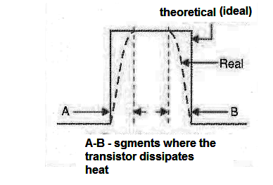
The less time they spend in this transition, the lower the power dissipated and the higher the efficiency, hence the need to use fast transistors in these circuits. The amount of transitions also influences this performance, so that a higher sampling rate also implies higher dissipation.
The commercial circuits are able to reconcile fast sample rates with good performance, reaching values as high as 88%.
G and H Classes
Other configurations for amplifiers have been announced by some electronic device manufacturers. One of them is the configuration called Class G Amplifier developed by Hitachi. In this configuration two sets of output amplifier transistors operate.
One set is fed with a lower voltage and the other set with a higher voltage.
When the amplifier works with weak signals, they are amplified by the lowest voltage supply stage and when the signals must reach the peak of power, they are amplified by the stage that works with high voltage. In Figure 19 we have an output stage of a Class G amplifier.

The idea of the Class H amplifier was launched by a company called Soundcraft and is a variation of the Class G amplifier.
In this case, we also have two circuits working on different voltages. However, when a cycle of a signal must be amplified, the initial part when the voltage rises is amplified by the stage of lowest power. When the signal strength reaches the saturation point of this stage, the circuit switches automatically, and the rest of the cycle is amplified by the stage of highest power. For a Class H amplifier we have an example of an output stage in Figure 20.

Conclusion
The modern applications where high performance and good fidelity are combined opt mostly for Class D or PWM stages. Dedicated integrated circuits from several manufacturers are currently available for projects. For sound devices where power and performance are no longer the main goal, but rather the highest fidelity possible, other stages can be found.


