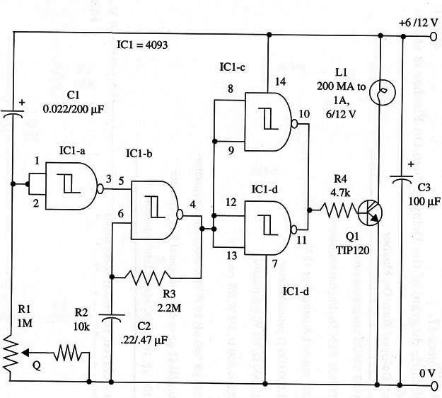
As in many projects using the 4093 shown in this site, the time delay and flash rate can be altered by changing the values of capacitors C1 and C2.
Transistor Q1 must be mounted on a heatsink, and the lamps can range from 50 mA to 1 A.
A schematic diagram of the Delayed Turn-On Flasher is shown in Fig. 1.

For a delayed turn-on, intermittent relay, replace L1 with a 6 V or 12 V, 100 mA to 500 mA coil relay.
Contacts must be selected according the load you intend to control.
IC1 4093 CMOS integrated circuit
Q1 - TIP120 N PN Darlington transistor
L1 - 200 mA to 1 A lamp, 6 or 12 V (see text)
R1 - 1,000,000 ohm - potentiometer
R2 - 10,000 ohm, 1/4 W, 5% resistor
R3 - 2,200,000 ohm, 1/4 W, 5% resistor
R4 - 4,70 ohm,, 1/4 W, 5% resistor
C1 - 100 µF/220 µF, 16 WVDC electrolytic capacitor
C2 - 0.22/047 µF ceramic or metal film capacitor
C3 - 100 µF, 16 WVDC electrolytic capacitor


