The power supply can range from 6 to 12 V, and current requirements are very low when the relay is off.
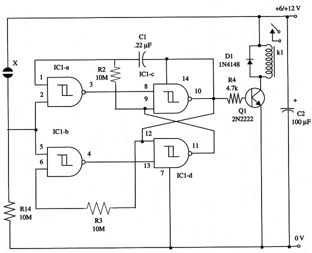
Two of the four gates of a 4093 are used as a trigger from a touch sensor. This circuit triggers a flip-flop formed by the other two 4093 gates. A transistor in the flip-flop output drives a relay from the existing logic level.
Sensitivity is determined by resistor R1, and you can vary it in the range between 100 kΩ and 10 MΩ according the application you have in mind. Higher values give greater sensitivity.
You can also replace R1 with a 10 M Ω potentiometer to obtain sensitivity control for the circuit.
The power supply choice is determined by the relay. For 12 V applications, you can use a mini 1 A DPDT relay, but any relay with 6 V or 12 V coils and a current drain from 10 mA to 100 mA can be used in this project.
A schematic diagram of Touch Activated Relay II is given in Fig. 1.

Proper positioning of the polarized components (diode, electrolytic capacitor, transistor) must be observed. Sensor X1 is made as described in other projects using touch sensor found in this site.
Short wires are preferable to connect this sensor to the circuit. Longer wires to the sensor should be shielded. Connect the shield to the positive power supply line. Change R1 according the desired sensitivity or replace it with a 10 M Ω potentiometer.
If you want to control heavy-duty loads, use a 10 A mini SPST relay. Don’t power the circuit from a transformerless power supply, as they don’t provide isolation from the ac power line, and this can result in a severe shock hazard when someone touches the sensor.
IC1 - 4093 CMOS integrated circuit
Q1 - 2N2222 NPN general purpose silicon transistor
D1 - 1N4148 general purpose silicondiode
X1 - Touch sensor, as in Project 74
R1, R2, R3 - 10,000,000 Ω, 1/4 W, 5% resistors
R4 - 4,700 Ω, 1/4 W, 5% resistor
C1 - 0.22 µF ceramic or metal film capacitor
C2 - 100 µF, 16 WVDC electrolytic capacitor
K1 - 6 V or 12 V relay (see text)


