As the current drain is higher in this version, a power supply is recommended. Thus, it is best to use the unit as a fixed device supplied from the power mains.
T the frequency range can be altered by changing Cl. Capacitors up to 2 µF can be used, producing very low frequency clicks.
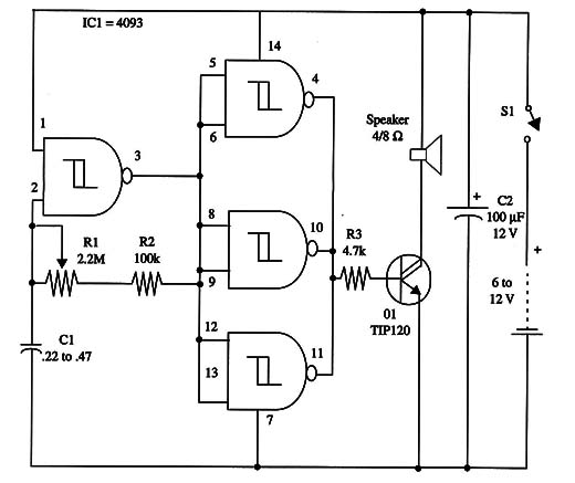
The complete schematic diagram of the Metronome is shown in Fig. 1.

Transistor Q1 must be mounted on a small heatsink.
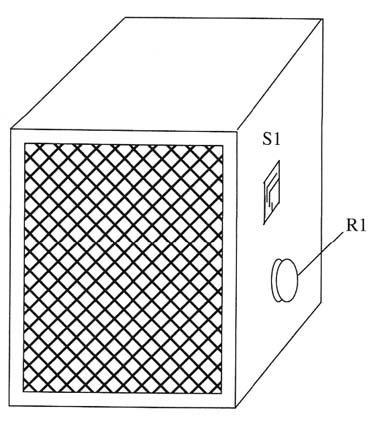
For best sound level the speaker should be installed into a loudspeaker enclosure.
This enclosure can also be used to house all the other components as shown in figure 2.

Loudspeaker and circuit are housed in the same enclosure, as shown above.
IC1 - 4093 CMOS integrated circuit
Q1 - TIP120 or equivalent Darlington power transistor (Or power-FET)
SPKR - 4/8 ohm, 2- to 4-inch loudspeaker
S1 - SPST switch
B1 - 6 V to 12 V power supply
R1- 2,200,000 ohm, 1/4 W, 5% resistor
R2 - 100,000 ohm, 1/4 W, 5% resistor
R3 - 4,700 ohm, 1/4 W, 5% resistor
C1 - 0.22 µF or 0.47 µF ceramic or metal film capacitor
C2 - 100 µF, 12 WVDC electrolytic capacitor


