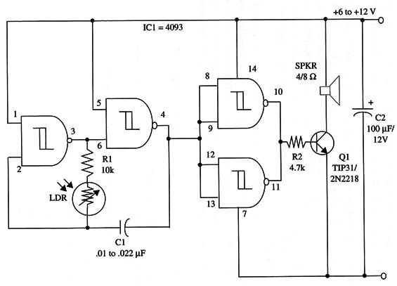
The circuit can be powered with voltages between 5 and 12 V. If using 9 V to 12 V supplies, the transistor must be mounted on a heatsink.
The frequency range depends on Cl and the amount of light on the sensor.
You can alter the frequency range by changing C1. Values in the range between 0.01 and 0.022 11F will produce sounds in the audio range.
If you want to produce “clicks,” with a rate depending on the amount of light on the sensor, you could experiment with capacitors in the range between 0.22 and 1 µF.
Metal film or ceramic capacitors ca be used in this experiment.
You can produce musical tones by moving your hand in front of the sensor, controlling the amount of light on it. Another interesting application is a light-frequency converter, sending information corresponding to light intensity to a remote frequency counter.
A correspondence table with values of frequency and amount of light should be used for the remote reader.
A schematic diagram of the device is shown in Fig. 1.

Transistor Q1 depends on the power supply voltage. If you’re using voltages between 6 and 9 V, the recommended transistor is the 2N2218 with a small heatsink.
If you’re using voltages supplies between 9 and 12 V, the recommended transistor is the TIP31 with a heatsink.
Light
1C1 - 4093 CMOS integrated circuit
LDR - Photoresistor LDR, Radio Shack 276-1657 or equivalent
SPKR - 4/8 ohm loudspeaker
Q1 - TIP31 or 2N2218 silicon medium power transistor (see text)
R1 - 10,000 ohm, 1/4 W, 5% resistor
R2 -4,700 ohm, 1/4 W, 5% resistor
C1 - 0.01 to 0.022 µF metal film or ceramic capacitor
C2 -100 µF, 12 WVDC electrolytic capacitor


