

Automatic gates or doors, safes or even places where things are stored that are not to be accessed by anyone can count on an automatic lock that is activated only when a specific key operation is taken.
In our case we propose a simple circuit in which two keys (from a set of additional keys that can be added to confuse the intruders) are tightened for an instant in a relatively short time interval. This range can be changed by simply changing values of certain components.
If the activation of these switches occurs within the prescribed range, the circuit activates a relay for a certain time which can also be adjusted according to the application. The relay can then be used to release a lock or call someone who gives access to the place. Other keys that are not used as a password can be linked to an alarm system.
The circuit is powered by a voltage of 12 V that can come from a small source, since the consumption is low. In the standby condition, in fact, the current demanded by the circuit does not represent appreciable energy consumption since it is less than 1 mA.
In addition to the security key, this setting can also be used in games and even in simultaneous signal detection devices.
HOW IT WORKS
When S1 is pressed, the capacitor C2 that is discharged is virtually charged with the voltage of the power supply, and then slowly discharges through the resistor R4. With C2 discharged, the level of pin 2 of the integrated circuit is low, but with discharge, the level will become high for a certain time.
Likewise with C1, so that after pressing S2 for an instant, pin 1 of the integrated circuit will remain at the high level for a certain time.
When the two switches are activated one after another, there will be a certain time interval between the two inputs of the integrated circuit (pins 1 and 2) and the output (pin 3) will go low. With this, we will have low level in inputs 5 and 6 of the next port which takes its output to the high level, polarizing the diode D1 in the direct direction.
Note that this is the necessary condition for D1 to be directly polarized. If S1 or S2 are pressed alone this does not occur and neither will occur if one of the capacitors is already discharged when the other is charged, hence the minimum sequential drive time. With direct polarized D1, the capacitor C3 charges and starts to discharge as soon as we no longer drive the diode (by the discharge of the input capacitors).
However, the discharge time of C3, given by its value and the setting of P1, will polarize the following inverter ports so that they keep the transistor conducting and therefore the relay driven.
Then see that to trigger the relay for a fixed time (determined by C3) it suffices that we have the drive of S1 and S2 for a time just enough to get a pulse on pin 4 that carries C3. The main components that can be changed are precisely the capacitors: C1 and C2 determine the time we have for the activation of the keys next, while C3 determines the activation time of the relay. C1 and C2 may be increased up to 470 nF typically, while C3 may have up to about 100 uF for a few minutes drive. We can also increase P1 to 2.2 or even 4.7 M ohms for a longer time.
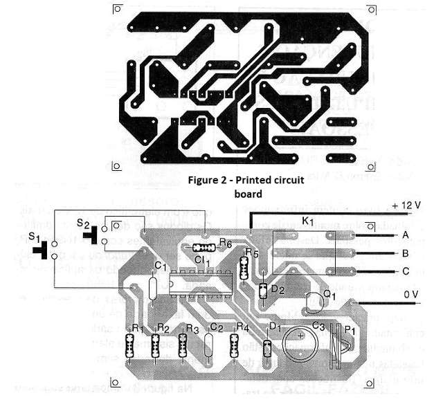
ASSEMBLY
In figure 1 we have the complete diagram of the security key in its basic version.

The relay can be of any economic type for 12 V and its contacts depend on the current of the system that must be actuated. The indicated type has 10 amp contacts. If the type is different we must change the printed circuit board design for your installation.
Another interesting possibility of adaptation to this circuit would be to add a NAND gate of more than 2 inputs and instead of using the first one of this circuit, we have a system in which 4 keys must be actuated.
The resistors are all 1 / 8W or larger and the capacitors are ceramic or polyester except C3 which is an electrolytic of 12V or more. The diodes are commonly used admitting equivalents like the 1N914 and P1 both can be a trim pot as a potentiometer depending on the intended application.
Pressure switches may be part of a keyboard where the others are used to trigger an alarm system or simply left without any connection. In figure 3 we give a suggestion of power supply for this circuit where the transformer has secondary of 12 + 12V with at least 300 mA.
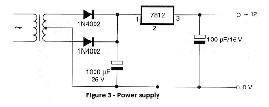
Power supply capacitors have minimum working voltages indicated in the diagram and the diodes admit equivalent. The circuit can be installed in a small metal or plastic box with the front keyboard of the drive. Care should be taken with the relay outputs and source input since they operate with the mains voltage.
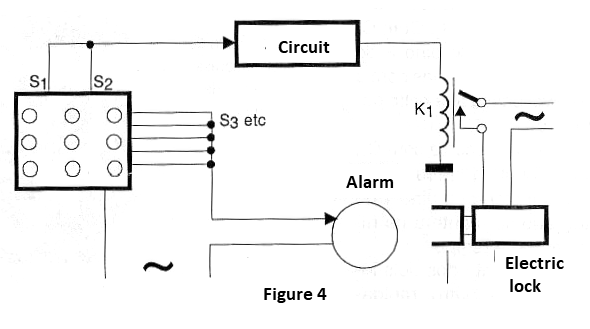
In figure 4 we give the way to make the connections of the system to activate an electric lock of a gate.
TEST AND USE
To test the circuit simply connect it to a power source and then quickly press S1 and then S2. The relay must be triggered for a period of time that can be set at P1.
Change the values for C1 and C2 if you have difficulty getting a precise trigger. Change C3 if you want to change the relay trigger time to a value that is not reached by setting P1. Once the operation is confirmed, it is only to make the installation final.
Semiconductors:
CI-1 4093B - CMOS integrated circuit
Q1 - BC548 - NPN general purpose transistor
D1, D2-1N4148 - general purpose diode
Resistors: (1/8W, 5%)
R1, R3 - 22k ohm
R2, R4 - 1 M ohm
R5 - 10 k ohm
R6 - 2.2 k ohm
P1 - 1 M ohm - potentiometer or trimpot
Capacitors:
C1, C2 - 100 nF - ceramic or polyester
C3 - 4.7 uF or higher - electrolytic - see text
Several:
S1, S2 - Pressure switches NA or keyboard - see text
K1 - 12 V relay - or equivalent
Printed circuit board, mounting box, integrated socket, button for potentiometer, wires, solder, etc.


