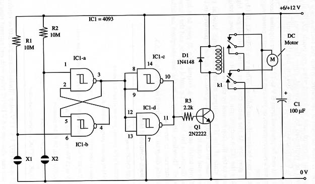
The circuit can be powered from 6 V to 12 V power supplies according the motor,s requirements, or you can use a separate power supply for the motor.
Operation can be described as follows. When you touch X1, IC 1-b input (pin 6) goes low. At the same time, its output (pin 4) goes high.
This makes the IC1-a output (pin 3) change its state to low, giving a stable state to the flip-flop formed by the two gates.
The low state of the IC1-a output determines a high level at the transistor base, so the relay is energized. The motor is powered in the direct mode and runs forward.
Now, if you touch sensor X2, IC1-a output (pin 3) goes to a high level. That dictates a low level at IC1-c and d outputs, and the transistor Q1 is off. Therefore, the relay is in the non-energized condition, and the motor runs in reverse.
A schematic diagram of the circuit is given in Fig. 1.

Relay K1 is a DPDT 1 A, 12 V relay (Radio Shack 27 5-249 or equivalent), but you can also use a 6 V DPDT relay with coil current ranging from 10 to 100 mA. Contacts current are chosen according the motor’s requirements.
Proper positioning of the polarized components (electrolytic capacitor, transistor, and the diode) must be observed.
If you are using this project in a model railroad, you can make an interesting and sensitive sensor with conductive foam glued to the bottom of a boxcar. Contact With the sensor can reverse the train movement. Before installing the unit, be sure that the motor is wired to provide the desired direction of movement.
This circuit can be also used as a Shield for microcontrollers such as the Arduino, PIC and others. You can use pins 1 and 6 to control the relay powering the IC with a 5 V supply.
IC1 - 4093 CMOS integrated circuit
Q1 - 2N2222 NPN general purpose silicon transistor
D1 - 1N4148 general purpose silicon diode
X1, X2 - Sensors (see text)
K1 - 6 V or 12 V relay, Radio Shack 27 5-249 or equivalent (see text)
M - 6 V or 12 Vdc motor (up to 1 A)
R1, R2 - 10,000,000 ohm, 1/4 W, 5% resistors
R3 - 4,700 ohm, 1/4 W, 5% resistor
C1 - 100 µF, 16 WVDC electrolytic capacitor


