The circuit is powered by common cells and is specially indicated for proto-board assembling or printed circuit board. This project is ideal to be presented in science fairs, expositions or as a scholar work.
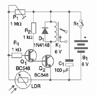
The relay used in the original project can control loads up to 2 A, but this component can be replaced by others rated to higher currents. The circuit is powered by a 6 V supply and the sensor is a common LDR (Light Dependent Resistor), and that adds high sensitivity to the application.
The sensitivity can be adjusted by a potentiometer according to the application. When the relay is off, the current consumption is very low. When the relay is on, the circuit drains about 100 mA. If the relay needs to spend a lot of time on, it is recommended the use of an AC/DC converter (power supply connected to the AC power line).
To achieve more directivity and sensitivity, the LDR can be installed inside a cardboard tube, with a convergent lens in one end. Figure 1 shows the complete diagram for the Light Activated Switch.

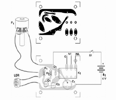
The components can be placed on a printed circuit board (PCB) as figure 1 shows.

The transistor can be replaced by equivalents and the LDR can be connected to the circuit using long wires, up to 10 meters long. S1 is optional if the device is only used for demonstration purposes. In this case it can be turned off by removing the cells from the holder.
In order to test the device, you just power it on and adjust P1 to keep the relay off when light falls upon the LDR. When light is cut, the relay must turn on. The contacts of the relay can be connected to any load you desire to control.
Competition
- Give a prize to the competitor who creates the best alarm system using this circuit.
- Give a prize to the one who makes the most sensitive device. Use a match to make the test, verifying the largest distance the flame can be detected, turning on or off the relay.
Q1, Q2—BC548 or equivalent—any general purpose silicon NPN transistor
D1—1N4148 or equivalent— any general purpose silicon diode
R1, R2—1 k ohm x 1/8 W resistor (brown, black, red)
P1—1 M ohm potentiometer—lin or log
LDR—any common LDR (1 cm or larger)
C1—100 ?F x 12 V electrolytic capacitor
K1—6 V x 50 to 100 mA relay (DIL base)
S1 - On/Off switch (SPST)
B1—6 V—4 AA, C or D cells—with holder –also an AC/DC converter can be used
Other:
Printed circuit board, solder, box to house the circuit, wires, etc.


