Note: this project was included in my book Science Fair and Technlogy Projects published in USA.
In Robotics and Mechatronics, the device can be used to remote control simple functions, like to activate a robot or power on an automatism. An interesting application for the circuit is an alarm activated when someone turns on a light or turns on a light torch.
Another application is as a solar alarm, activating a radio or a buzzer when the sun rises. As a final observation, we can say that the device consists in a circuit that turns on a relay when the sensor is illuminated.
How it works:
An interesting point to raise in this project is the use of a common 2N3055 transistor as a photo-sensor. We just have to remove the metallic cover of the transistor and expose the chip to the light. This fact proves that any silicon junction, like the ones found in any transistor, is sensitive to light.
When those junctions are illuminated, charge carriers are freed, resulting in a weak current through the device. This current can be amplified enough to activate a relay, as we do in the project. The relay consists in an electromagnetic switch capable of turning on and off an external load, like a circuit powered from the AC power line.
The recommended relay can control loads up to some amperes but it can be replaced by a small lamp. So, when the circuit is activated, the lamp will light up. This solution is recommended for demonstration purposes. The power supply consists in common cells or an AC/DC converter.
Building:
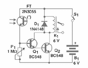
Figure 1 shows the complete schematics diagram of the project

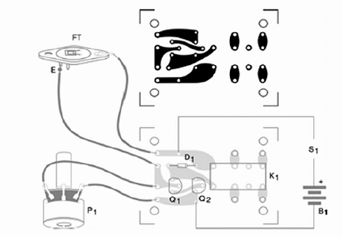
The components can be placed on a printed circuit board (PCB) as shown in figure 2.

The photo sensor (Q1) can be placed away from the board using a long pair of wires.
Any type of sensitive relay rated to coil currents up to 100 mA can be used in this project. The board has a lay out designed for DIL types, but you can use other types if you change the board. P1 adjusts the sensitivity.
The transistors and even the FT (Photo Transistor) can be replaced by equivalents. If you have one, you can use any common photo-transistor, carefully observing the terminals identification. You’ll find a 2N3005 in many old appliances like audio amplifiers, TVs, etc.
Remove it from the heatsink where it is installed and carefully remove the cover to expose the silicon chip. If the transistor is good, the device will work. The controlled load is connected to points A, B and C. Using a SPDT (reversible), it is possible to turn on or turn off when the circuit receives light.
Remember that the circuit is a momentary action type, keeping the relay on only during the time the light is falling onto the sensor.
Using a LDR
If you cannot find a 2N3005 to be used in this project, it can be replaced by a common LDR (Light Dependent Resistor). In some cases, you can get better sensibility than reached in the original project.
Testing and Using
In order to test it, you just have to adjust P1 to a point near the trigger (turn P1 back a little bit to turn it off, right when it turns on). Then, by illuminating FT, the relay will trigger producing a little ‘click’. Connect the outputs of the relay to lamps, motors and other appliances to demonstrate its operation. You can increase the sensibility by installing FT inside a small cardboard tube with a convergent lens in the front end. The transistor must be placed near the focus point of the lens. Try the position adjustment until you find the best performance.
What you have to explain:
If you intend to use your project in demonstrations or classes, you will need to know exactly how to explain, presenting the operation principle and making technical explanations. Explain the operation principle of silicon photo-sensors and the Einstein Effect if your public has the level to understand this. Show how the current flows across the sensor when it is illuminated.
You can also explain how these sensors are used in alarms, automatic door openers, remote controls and talk about the type of radiation it can sense too. Show that these sensors also sense infrared and ultraviolet radiation. This allows their use in invisible alarms or alarms that sense heat.
Giving Robotics and Mechatronics applications, you can indicate the position sensors and the obstacles sensors. An array of theses sensors can be used as an electronic eye, like the one found in CCDs of digital cameras.
Additional Works
Prepare a stand where the photo sensors point to a place visitors use to pass through. Also point to this place the beam of a directional common lamp. When anyone using clear clothes (that reflect light) passes in front of the sensor, the reflected light will trigger the circuit. Connect a buzzer to the relay to produce a loud sound.


