Any audio device with a phone output can be plugged to this booster to achieve a loudspeaker listening. Using a good loudspeaker, with 10 cm or more (4”) inside a good acoustic box, the sound quality will be very high.
The power supply for this amplifier must source 6 V to 9V with current rates starting from 500 mA. The circuit uses only one transistor as active element, and if you intend to use the unit with stereo equipments, you will need two circuits like this, one for each channel.
Only one adjustment is needed to bias the circuit to the lower distortion point.
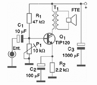
Figure 1 shows the complete diagram for the Audio Booster.

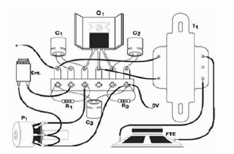
If your audio equipment is stereo, you have to assemble two stages like this, but you can only use one power supply for the two. Figure 2 shows the component placement on a terminal strip.

Q2 is a power Darlington transistor and the original type can be replaced by equivalents. In fact, any NPN Darlington transistor having a collector current rated to 4A or more can be used. This transistor can be assembled on a small heatsink.
The resistors are all 1/8 or 1/4 W types, presenting any tolerance. The electrolytic capacitor has 12 V or more of working voltage. The transformer is a small audio output type with 200 to 1000 Ω of primary and 8 Ω of secondary.
This transformer can be found in some audio appliances, like radios, tape recorders, intercoms, etc. If you cannot find this component, you can try a small power transformer with a primary of 110/127 V and a secondary of any voltage between 3 and 12 V with currents starting from 200 mA.
Once you have completed you assembling, connect it to a power supply and place P1 in the medium position. Connect any audio source like a small transistor radio to the input of the booster. The signal is picked up from the phone output of the radio. Use an appropriate plug for this task.
Then, adjust P1 and the volume control of the audio source until you have a clear reproduction by the loudspeaker. If you power the circuit from cells, use C or D types, since the current drain is high and smaller types like the AA can run down fast.
Semiconductors:
Q1—TIP120—Power Darlington silicon NPN transistor—or equivalent
Resistors: (1/8 W, 5%)
R1—47 k ohm—yellow, violet, orange
R2—22 ohm—red, red, black
P1—10 k ohm—trimmer potentiometer or common potentiometer—lin or log
Capacitors:
C1—10 ?F x 12 V—electrolytic
C2— 100 ?F x 12 V—electrolytic
C3—1,000 ?F x 12 V—electrolytic
Other:
T1—Audio Output Transformer—see previous text
FTE—4 or 8 ohm—10 cm or large—small loudspeaker
Terminal strip, Acoustic box, heat sink for the transistor, power supply, wires, solder, cable with plug according to the audio source, etc.


