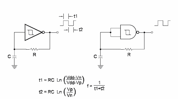
The advantages of using Schmitt Inverters (74108) or Schmitt NAND gates (4093) in oscillators lie in the need for a low number of external components and the snap action due to hysteresis that allows the production of high-quality square signals. The circuit shown here is the basic configuration using one of the four gates of a 4093 and one of the six inverters of a 40108. The frequency is given by the time constant Ro according to the formula in the diagram. In the formula:
T is the total period in seconds [s]
T1 is the period to the output in the high level in seconds [s]
T2 is the period for the output in the low level in seconds [s]
R is the resistance in Ω [0]
C is the capacitance in farads [F]
Vdd is the power-supply voltage in volts [V]
Vp is the positive threshold voltage in volts [V]
Vn is the negative threshold in volts [V]
The resistor can be replaced by a trimmer potentiometer to perform as a variable oscillator. A 100 k ohm trimmer potentiometer in series with a 10 k ohm resistor is suggested for a practical application in the audio range. The lowest value recommended for C is 47 pF and for R is 1 k ohm. The highest value of the components depends on the losses of C.


