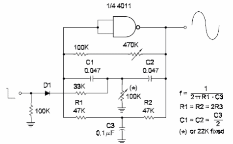
The circuit shown here can be used to produce low-frequency sine wave signals from CMOS logic. The frequency depends on the Twin-T network and is calculated by the formula given with the diagram. The ratio of values between the capacitors and resistors may be observed. The circuit is controlled by an external logic signal applied to the input. The input resistor [27 k ohm] can be changed to modify the damp effect of the control signal. Damped signals can also be adjusted replacing the 100 k ohm resistor between the capacitor in the twin-T network by a trimmer potentiometer. When designing a circuit to any other frequency, keep the resistors with the values as recommended in the diagram and calculate the capacitor according to the desired frequency.


