The amplified signals can then be applied to the input or antenna of the receiver with which it will operate. Grounding is very important for maximum circuit performance.
The transistor used can be any type of RF such as the BF494 or its equivalents.
ASSEMBLY
In figure 1 we have the complete diagram of the apparatus and in figure 2 its assembly realized in a bridge of insulated terminals.


The appliance can be installed in a closed box for ease of use. The resistors are 1/8 W or larger and the capacitors must all be ceramic.
In figure 3 we have two ways of connecting the amplifier to the receivers.
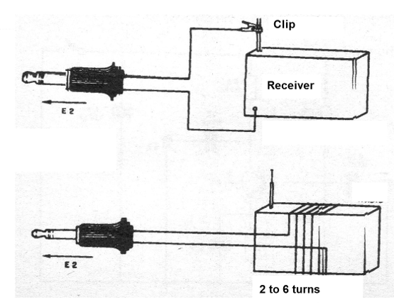
The first is for receivers that have antenna and ground input. If the earthing is not accessible, it can be made at the negative pole of the battery holder or at any point in its chassis that corresponds to earth.
The second is for receivers without antenna. In this case, we make a radiating "frame antenna" which consists simply of rolling 2 to 8 turns of ordinary wire around the radius. The external antenna must be at least 5 meters long and the ground connection can be made in a water pipe, at the neutral pole of the outlet or in an iron bar buried in the ground. If you do not get amplification when you connect, reverse the connections of the plug that goes to the antenna.
Q1 - BF494 or equivalent - RF transistor
C1, C2-10 nF - ceramic capacitors
C3 - 1 nF - ceramic capacitor
C4 - 100 nF - ceramic capacitor
R1 - 1 M - resistor - brown, black, green
R2 - 100 k - brown, black, yellow
B1 - 9 V - batteries or battery
S1 – On-Off switch
E, E2 - Input and output jacks
Several:
Terminal bridge, battery holder or battery connector, wires, solder, etc.