

The circuit that we present aims at the use of a small transistor radio speaker out of use as a microphone or even transducers of musical toys (key chains, space weapons or dolls) since they have low impedance in the same function.
The transmitter operates in the FM range and can be used in play, such as a microphone, or even as a short-range communication system. Your signal can be picked up on any FM radio at a distance of up to 30 meters. Simple to assemble, the device uses few components and can be powered with 2 or 4 common batteries and up to a 9V battery with some component value changes.
The circuit can even be used in espionage, because hidden in objects of common use can transmit the conversation of people who are nearby.
Features:
• 3 to 9 V supply voltage (2 or 4 cells or battery)
• Operating frequency: 88 to 108 MHz (FM) or 50 to 120 MHz (VHF)
• Range: 30 meters (typical)
• Microphone Impedance: 4 to 200 ohm
HOW IT WORKS
Low-impedance transducers, such as small speakers when used as microphones, have very low throughput, so the available signal is a voltage that does not exceed a few millionths of a volt. This voltage is insufficient to modulate a transmitter even of small power, if it does not pass before by a good amplification.
The best way to amplify weak signals from low impedance sources is through a connected transistor stage in the common base configuration. This is what we do in our project: the signal being amplified enters the emitter of the transistor and is withdrawn amplified from its collector.
The base of the transistor is biased by resistor R1. The capacitor C1 has the function to decouple the transistor that allows it to respond to the rapid variations that correspond to the audio signals. In this way, the signal obtained from the speaker, when it picks up some sound, is applied via C3 to the transistor and then amplified is applied to the next step of the transmitter via C2.
The high frequency circuit which produces the signals to be transmitted is based on the transistor Q2. In this circuit the signal frequency is determined by L1 and the CV setting. Changing the number of L1 turns can also cause the transmitter to operate in the VHF range below the FM range of 50 to 88 MHz and even in the upper range of 108 to 120 MHz.
Of course, in this case, the reader must have a receiver that receives the signals at the chosen frequencies.
The capacitor C5 has the function to do the feedback that keeps the circuit in oscillation. The resistors R4 and R5 determine the base bias of the transistor.
The emitter resistor also determines the signal strength, but should not be changed other than for 9V battery use. In fact, with this battery, to avoid overloading the transistor, it should be increased to 100 ohm.
If the reader wants more power, hold the resistor, replace the transistor with a BD135 and power the circuit with 9 or 12 V in case its range can rise to 500 meters or more, depending on the antenna and receiver sensitivity and congestion of the FM band in your locality. Connecting the antenna to a coil outlet improves the stability of the circuit by better matching impedances.
ASSEMBLY
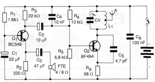
In figure 1 we have the complete diagram of the transmitter.
In Figure 2 we have the arrangement of the components on an improper circuit board.
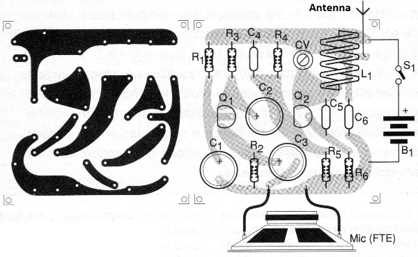
This type of assembly makes it easy to place the device in a small plastic box. Do not use a metal housing to prevent the circuit from being unstable.
For the FM range the coil L1, formed by 4 turns of common or enameled wire 22 or thinner in a pencil as a shape. the antenna is connected in the second turn on the side of the transistor.
For the 50 to 80 MHz range use 5 to 7 turns and for the upper range 1 or 2 turns. The CV trimmer can be of any type with maximum capacitances in the range of 20 to 50 pF. This component is not critical as we can compensate for its effects on coil turns.
The capacitors with the lowest values are of the ceramic disk type, while the largest ones (C1, C2 and C3) are electrolytic for 6 V or more of working voltage.
All resistors are 1/8 W or larger with 5% or more tolerance. The antenna is a piece of rigid wire stretched from 20 to 50 cm long or a telescopic antenna of the same length. As a microphone we use a small 2.5 to 5 cm (FTE) loudspeaker that can be obtained from any out of the box device.
Another option is a low impedance phone capsule or even a magnetic recorder microphone.
TEST AND USE
To test the transmitter, connect a free-range (off-station) FM receiver nearby.
Get away with the transmitter in your hand from a distance of about 3 meters and adjust CV with a non-metallic wrench until you pick up the signal of greater intensity. See that two or more (harmonic) signals can be picked up and what matters is the fundamental, which has greater reach.
Speak into the microphone to check playback. If there is overdrive talk farther from the microphone or change the value of R3 that can be between 10k ohm and 22k ohm. Checking the transmitter operation, move farther away and ask to better tune the tuning while speaking until you get the best performance.
Check your reach by going as far as possible. Avoid shaking the antenna too much so that the circuit does not disturb the signal by escaping the tuning.
In the open field the range is greater because there are no obstacles to its propagation. With 6-volt power the range can easily reach 30 meters. To use just talk in front of the microphone, avoid touching the antenna.
Look for the microphone distance that results in clearer playback without distortion.
Semiconductors:
Q1 - BC548 or equivalent - NPN general purpose transistor
Q2 - BF494 or equivalent - RF transistor
Resistors: (1/8 W, 5%)
R1 - 1 M ohm - brown, black, green
R2 - 330 ohm - orange, orange, brown
R3 - 22k ohm - red, red, orange
R4 - 10 k ohm - brown, black, orange
R5 - 6.8 k ohm - blue, gray, red
R6 - 68 ohm - blue, gray, black
Capacitors:
C1 - 22 uF / 6 V - electrolytic
C2 - 10 uF / 6 V - electrolytic
C3 - 47 uF / 6 V - electrolytic
C4 - 10 nF - ceramic
C5 - 4.7 pF or 5.6 pF - ceramic
C6-100 nF - ceramic
CV - common trimmer - see text
Several:
L1 - coil - see text
FTE - Small 4 or 8 ohm speaker or low impedance capsule up to 200 ohms
S1 – On/Off switch
B1 - 3 or 6 V - standard batteries (or 9 V battery - see text)
A - antenna - see text
Printed circuit board, support for two or four batteries or battery connector, mounting box, wires, solder, etc.


