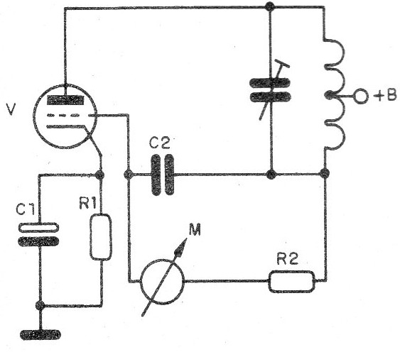
The dip-meter had its origin in 1947 (when an oscillator circuit was first published using the triode valve) and could be used to verify the resonance of circuits, according to the configuration shown in Figure 1.

This oscillator circuit had a current meter connected to the grid to monitor the current in this element.
When the oscillator circuit was placed in the vicinity of a circuit which resonated in its frequency, or an oscillator operating at its frequency, there was an absorption of energy which affected the grid current, that was immediately indicated by the meter.
This way, it was enough to approach the circuits analyzed to verify what happened with the grid current.
Since valves were used and the valves had control grids, the circuit was called a grid-dip meter, since the current in this element "dipped" decreasing sharply of value.
Nowadays, the same circuits can be made using common modern components such as bipolar transistors and field effect transistors.
Of course, we will no longer have grid-dip meters, but rather, dip-meters, because we can keep measuring the current which falls in the resonance, although not in the grid, but in another element of the circuit.
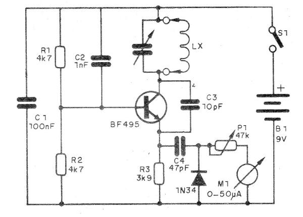
For an NPN transistor, we can have a circuit as in Figure 2.

With a BF494 or BF495 or even 2N2222, we can work with frequencies in the range of about 10 MHz up to more than 200 MHz.
The operating frequency is determined by the coil and by the setting of the variable capacitor.
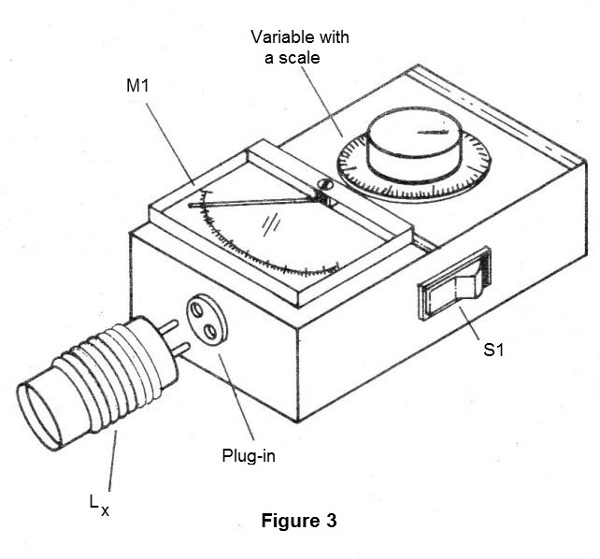
In Figure 3, we have the appearance of a dip-meter, noting that it has a set of coils for several frequency bands, which are embedded when we need them.

For a homemade construction of this device, the calibration can be made based on the scales of a common shortwave radio or an FM receiver.
The use of this device is very simple: we put the coil which must cover the desired band and approach it to the circuit which we wish to verify resonance or oscillation.
We slowly rotate the variable CV until the indicating instrument needle shows a drop in current intensity.
At this point, simply read at the calibrated scale the frequency of oscillation or resonance of the circuit.
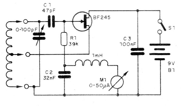
In Figure 4, we have a version with a junction field effect transistor.

Figure 4 - Circuit with JFET
The shock of 1 mH can be wound with 120 to 150 turns of very fine enameled wire (32 or 34) on a 100 kW ? resistor or even on a match.
The transistor used is BF245, but equivalents like MPF102 can be used.
In this case, we also have the possibility to change the coils which should form a set that goes from 100 kHz to 100 MHz.
For 100 kHz wind 200 turns of wire 25 in a 1.5 cm diameter tube without a core.
The socket will be made on all coils from 1/4 of the turns from the ground side.
We can say the grid-dip meter replaces in many applications a common frequency meter, especially when analyzing circuits in the bands of VHF and UHF.
The main advantage comparing with the frequency meter is that we can determine the resonance frequency of a switched circuit (parallel coil with capacitor).
Another advantage is the sensitivity which is greater than that of the common frequency meters.
How about assembling your grid-dip meter now?


