

The reed-switches or blade switches consist of devices formed by a glass bulb within which there are flexible blades made of materials that can undergo the action of magnetic fields. The glass bulb is filled with an inert gas in order to avoid the corrosive action of the air on the blades, which would affect the electrical contact in a short time.
In its simplest version we have two blades, assembled as shown in Figure 1.

Under normal conditions, the blades are separated and no current can flow through the component. It operates as an open key.
Approaching a permanent magnet of the device, as shown in Figure 2, the action of the magnetic field causes the blades to magnetize and thereby attract, uniting. In these conditions the electric contact is closed.
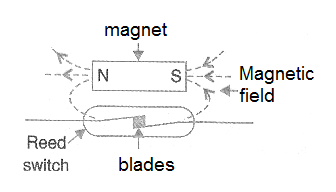
In other words, the reed-switch opens and closes its contacts according to the action of an external magnetic field.
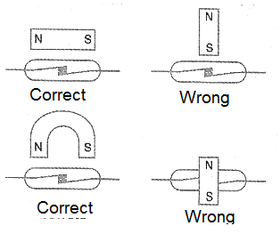
It is important to note that for proper action of the blades by closing the contacts the magnetic field must be correctly oriented. If the field does not magnetize the blades so that they attract, there is no key actuation. In Figure 3 we show the correct positions that must be used for permanent magnets to activate a reed-switch.
In addition to the basic type with two blades, we can find reed-switches that work as reversible switches. Thus, in the type shown in Figure 4 the action is of a 1-pole x 2-position switch.
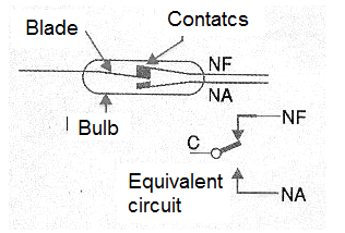
When there is no external magnetic field acting on the device, the C (common) contact remains connected to the NF (normally closed), as in a relay. When we apply a magnetic field, the blades magnetize and the movement of the contact C is in the direction of touching the NO contact (normally open). We then have the external circuit switched.
How to Use a Reed-Switch
Common reed-switches are low current devices. Common types are specified to control currents that do not go well beyond 200 mA.
Therefore, we must never use these components to directly control higher power loads, such as motors, solenoids, lamps whose currents are higher than the indicated values.
To control a larger load we have two possibilities which are shown in Figure 5.
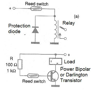
In one, we use the reed-switch to control a relay whose contacts can withstand the current drained by the load to be controlled. In the other we use the reed-switch to switch a transistor or other semiconductor which has the load controlled in its collector. The component bias resistor determines the current through the reed-switch.
The maximum stresses that this component supports when the contacts are open is also not the highest. Normally they should not be used with voltages above about 50 V typically. For larger values, the component specifications should be consulted.
Finally, the reed-switch is a component that has a relatively high response rate. We can use it to open and close contacts quickly by passing a fast magnetic field.
This allows it to be used as a rotation or motion sensor, as shown in Figure 6.
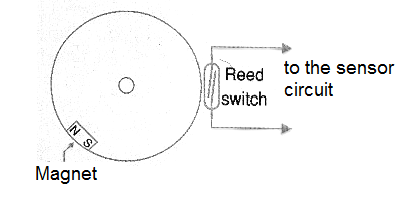
With each turn of the steering wheel, the small magnet passes before the reed-switch actuating. This produces a pulse which goes to a revolution counter. Up to 100 turns per second can be counted with a sensor of this type.
Practical Applications
We can use the reed switches in several interesting circuits for mechatronic applications. Let's give examples:
a) Reed-relay
By wrapping enamelled wire around a reed-switch to form a coil we can produce a sensitive relay, as shown in Figure 7.

The sensitivity of the relay will depend on the number of turns. For a 6 V sensitive relay, for example, we suggest rolling at least 500 turns of thin enameled wire (32 or 34 AWG).
This relay can be driven by sensitive sensor circuits, as shown in Figure 8, with the advantage of isolating the drive circuit from the driven circuit.

Just remember that the controlled load should not consume more than a 200 mA if a common low-current reed-switch is used.
b) Current Sensor
Wrapping a few turns of thick wire (24 to 28 AWG) around a reed-switch, as shown in Figure 9, we have a current sensor.

This sensor can be used to trigger a safety system when the current in a load (a motor, for example) exceeds a certain value. In Figure 10 we have a circuit for this purpose.
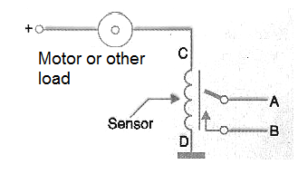
The drive current of the number of turns of the coil, in addition to the sensitivity of the reed-switch used. The reader must obtain the number of revolutions of the coil experimentally in function of the current that must be detected.
c) Proximity sensor
To detect the approach of an object or even a movement, simply use a reed-switch and a magnet, as shown in Figure 11.

The distance at which the trigger occurs depends on both the strength of the magnet and the sensitivity of the reed-switch. Note that this circuit can be used to detect through non-metallic objects.
We can use this configuration to detect the passage of a robot by a certain place, or to make its operation with a secret key, as shown in Figure 12.

d) Position sensor
Two or more reed-switches can be used to sense the position of a rotating object, a robotic head, for example, as shown in Figure 13.
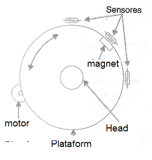
A small magnet is attached to the object to start the reed-switches in the indicated positions.
e) Switching key
A switching key can be made based on a set of reed-switches and a magnet attached to the control, as shown in Figure 14.

The great advantage of this key is that the magnet attached to the slider can stand on one side of a panel of insulation material and the reed-switches on the other side.
f) Rotation counter
Finally we have a circuit which produces pulses of constant duration from the passage of a magnet in front of a reed-switch. This circuit, shown in Figure 15, can be used as the basis for a speed counter or a speedometer.

The frequency of the pulses of the circuit is given by the rotation of the object. We can integrate these pulses and obtain a proportional voltage for indication on a common instrument, such as a milliammeter.
The output of this circuit is compatible to both TTL logic and CMOS.
Conclusion
Reed-switches are easy to get and inexpensive. The reader can craft many interesting devices using these switches as sensors, switches or relays.
In this article we have seen just a few of the many applications that the reader may have for these useful component.


