

Most of our readers are familiar with the Wheatstone Bridge, which is used in resistance measurements and works as a starting point for many instrumentation laboratory studies.
However, for this same majority, there are many other bridges that are unknown, but whose importance is no less than the Wheatstone Bridge itself.
It is these bridges that we are going to talk about in this article.
WHAT IS A BRIDGE
A bridge is nothing more than a measuring circuit which makes use of a signal source or a DC voltage and a null detector which can be a headset, a moving coil indicator or any other depending on the type of application required, as shown in Figure 1.
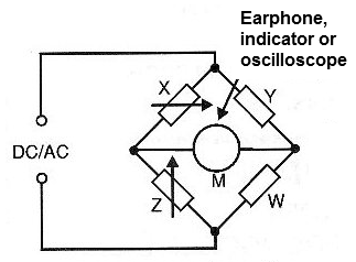
When the components of this bridge have a certain relation of values, there is no signal or no current flowing through the null detector.
It is said, under these conditions, that the bridge is in equilibrium.
If we have a component of unknown value, and we have a variable component which compensates its value, we can always obtain the balance of the bridge by adjusting the variable component.
This means that we can equip the variable component of a scale in such a way that allows us to determine the value of the unknown component when equilibrium is reached.
According to the components used, the type of magnitude that will be measured by the bridges receive several denominations that we now analyze.
THOMSON BRIDGE
This is a very interesting bridge, designed to measure very low resistances, less than 1 ohm.
This bridge receives the name of its discoverer who developed it in 1862, having the basic circuit shown in Figure 2.

The resistances of the circuit shall initially maintain the following ratios of values:
R1 = R3
R2 = R4
The resistance Ro is fixed and has a value that should be approximately the value of the resistance expected to be measured (Rx).
The resistors R2 and R4 are conjugated, or they vary at the same time by a single axis.
Under these conditions, the null of the bridge will be obtained when the resistances of the circuit satisfy the following equality:
Rx = Ro (R4 / R3)
The main advantage in using this type of bridge is that the influence of the resistance of the wires connecting to Rx can be eliminated, which is important when measuring very low resistances.
SAUTY BRIDGE
The Sauty Bridge has its circuit shown in Figure 3 and works for the measurement of capacitances.

What is done in this bridge is to exchange one of the resistors of the Wheatstone bridge by a capacitor and, in addition, a frequency signal is applied to the power according to the capacitors to be measured.
This way, the capacitive reactances of the capacitor to be measured and of a reference capacitor are used in the bridge equilibrium.
By calling Xc the capacitor reactance to be measured and Xo the reference capacitor reactance, the bridge equilibrium will be achieved when the following ratio of values between all bridge elements is satisfied:
R1
R2
=
Xc
Xo
Working with a high-impedance headset with signals in the range of 1 kHz to 5 kHz, the null detection is made at the point where the sound disappears.
For very small capacitances it is possible to use higher frequency signals and as a null detector an oscilloscope.
A problem which can occur in this type of bridge comes from the fact that the measured capacitor may not have a pure capacitance.
Remember that a real capacitor has a certain parasitic resistance in series to be considered.
A variable resistor can be added in series with the reference capacitor also to compensate for this parasitic resistance in case the equilibrium, when achieved, leads to both the determination of the capacitance Cx and the parasitic resistance connected in series, as shown in Figure 4.
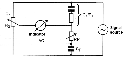
Sauty bridge variations exist to measure electrolytic capacitors in which case elements are added as a continuous bias source for this component, inductances and capacitances for the purpose of filtering continuous currents and signals used in the tests.
SCHERING BRIDGE
In Figure 5, we have the basic diagram of a Schering Bridge that is used to measure capacitances with excellent accuracy.
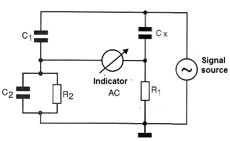
A characteristic of this bridge is that it allows the measurement of capacitors even if they leak, since it can be balanced as a function of the resistance parallel to the capacitor.
The signal source will depend on the values ??to be measured, as well as the null detector.
For common capacitors in the range of 1 nF to 1 uF you can use a 1 kHz signal generator and a headset as bridge elements.
The equilibrium of this bridge occurs when the following relations between the components are satisfied:
Cx = C1 (
R1
R2
Rx = R1 (
C2
C1
)
Where Cx is the capacitance of the capacitor under test and Rx is the leak resistance.
WIEN BRIDGE
An important feature of the bridges we have seen so far is that their equilibrium is independent of the frequency of the input signal.
For the measurement of audio signals, an interesting bridge, in fact that gave rise to the Schering Bridge, is the so-called Wien bridge, shown in Figure 6.
This bridge is balanced when a capacitor Cx acquires a value such that:
Cx =
1
(R1.R2.C1.ω)
Where: ω = 2. π . f, where f is the frequency of the signal.
If the capacitor used is variable, previously adjusted in function of the other elements can determine the frequency of the signal.
Making sure that:
R3 = 2.R4
C1 = C2
The balance of the bridge is obtained when:
f =
1
(2.π.Cx.R2)
See that this configuration is the same as that used in the so-called Wien bridge oscillators whose basic circuit of the loop is the feedback which determines the frequency shown in Figure 7.
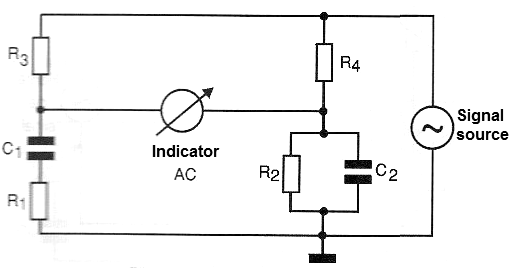
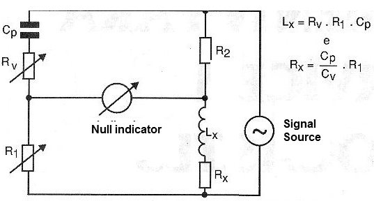
MAXWELL BRIDGE
This bridge, whose basic diagram is shown in Figure 8, is used as the inductance.
The basic idea is to compare an inductance with a capacitance, based on its reactances, because it is more difficult to obtain a pattern of inductances than of capacitances.
Thus, when this bridge is in equilibrium, we have the relation shown in the diagram itself.
The equilibrium occurs when the reactances, the coil and the reference capacitor, acquire values which maintain a ratio that depends on the values ??of the resistors of the other arms.
The frequency of the signal used depends on the order of magnitude of the inductance to be measured.
An improvement of this bridge is shown in Figure 9 in which a variable resistor is also added to the circuit.
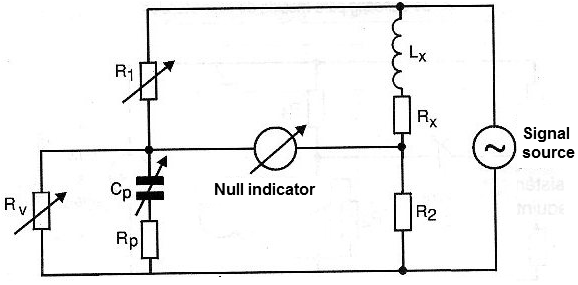
This component is necessary to balance the bridge taking into account also the ohmic resistance of the winding of the coil which adds to its inductance.
Remember that the coil is equivalent, in its actual circuit, to an inductance connected in series with a resistance.
Note that the balance of this bridge is made by means of two adjustments, and an important point is that, by measuring both the inductance and the associated resistance, one can also have an idea of ??its quality factor (Q factor).
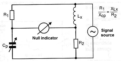
BRIDGE OF HAY
This bridge, whose basic diagram is shown in Figure 10, is also intended for the measurement of inductances.
The principle of operation is the same as the Maxwell bridge, using a capacitor to balance with its reactance, the reactance is presented by an inductor, which is being measured.
The balance of this bridge will be achieved when the ratio of component values shown in its diagram is reached.
OWEN BRIDGE
In Figure 11, we have the basic diagram of an Owen bridge that is intended for the measurement of inductances.
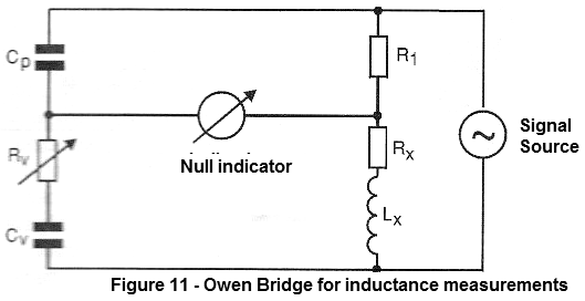
This bridge has the important characteristic that its operation does not depend on the frequency of the signal.
In the diagram we have the relation of values ??of components that must be satisfied so that it stays in equilibrium.
CONCLUSION
The bridges are of great importance in the laboratories of electronic measurements.
In this article we gave a small idea about its types and utilities.
However, the circuits indicated when taken to professional equipment may have important additional features such as sensitivity controls, selection of measured value ranges as well as null detectors with varying levels of sensitivity and others.


