A voltage comparator is more than an operational amplifier that has a very high gain and can operate normally with a simple power supply. We have basically two ways of using a comparator, which determine the type of output obtained.
In the first way, shown in Figure 1, we connect the comparator inverter input to a pair of resistors whose values will determine the reference voltage at that input.
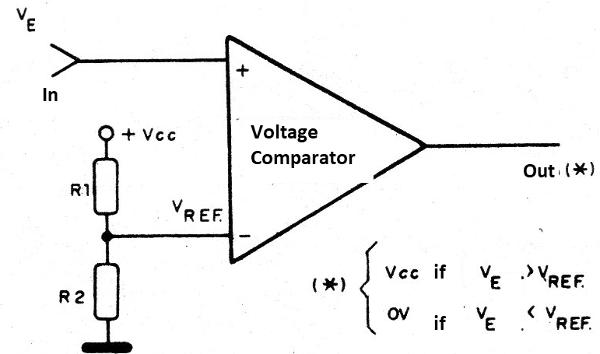
If we use two resistors of the same value, for example, the reference voltage will be half of the supply voltage or Vcc/2. For other value relations, for example using any R1 and R2, the reference voltage will be given by:
Vref = Vcc (R1/R1 + R2)
Another possibility of establishing the reference voltage is with the use of a zener diode, as shown in Figure 2.
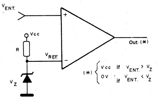
In the other input of the comparator, we apply the voltage to be compared, i.e., the input voltage. If this voltage is lower than the reference voltage, the comparator output will have a voltage very close to 0 V.
If this voltage is higher than the reference voltage, the comparator outputs will go to the high level, i.e., will have a voltage very close to the supply voltage. This behavior can be illustrated by a graph as shown in Figure 3.
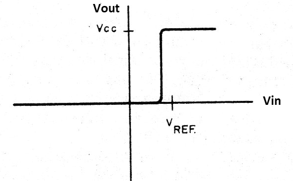
Note that in the region where the input voltages are very close, we have indefinite output behavior as the transition occurs.
The much high gain of the circuit makes this undefined range very narrow, with just a few millivolts or at most a few tens of millivolts. In the second mode of the operation, the reference voltage is applied to the non-inverting input (+) and the input voltage is applied to the inverting input, as shown in Figure 4.
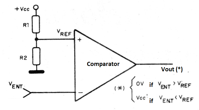
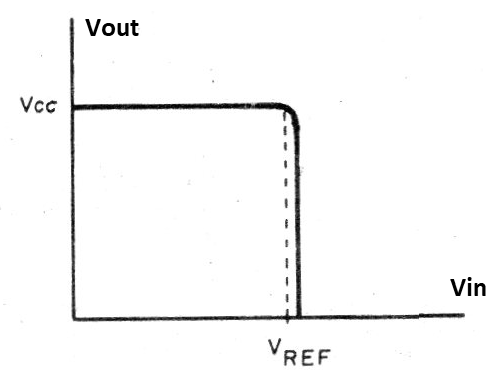
Under these conditions, if the input is less than the reference voltage, the output voltage will be positive, very close to the supply voltage. If the input voltage is greater than the reference voltage, the output voltage is very close to zero.
A graph representing this behavior is shown in Figure 5.
In practice, voltages cannot reach Vcc or zero due to losses in circuit components.
However, there are comparators where the voltage is very close to these values, which is why they are called rail-to-rail, i.e., the output voltage oscillates between the two supply lines (rail). The currents we can get from a comparator output are usually small, on the order of a few milliamps or just over a dozen milliamps, which allows only ordinary LEDs at most to be driven, as shown in Figure 6.
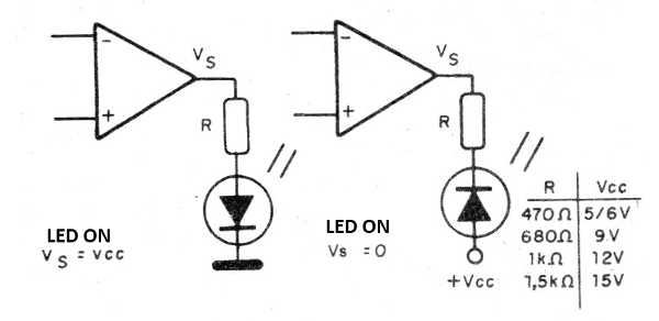
The resistor R has its value determined according to the supply voltage, so as to limit the LED current to a value that is within the limits of the comparator capacity. For a power stage, triggering relays, lamps or motors, for example, we can use the circuits in Figure 7.

In the first circuit we have loads up to 100 mA, when the comparator output is at the high level, that is, close to the supply voltage. In the second circuit, we have a load of the same order, when the output voltage is zero.
The third circuit corresponds to a higher power stage with a Darlington transistor, of the order of 1 A.
For a PNP (Positive, Negative, Positive) Darlington, we have a zero voltage drive, while in the example given, the triggering occurs when the comparator output is positive. Powering the comparator with a 5V source can drive TTL (Transistor-Transistor Logic) loads, and with other voltages we have CMOS (Complementary Metal-Oxide Semiconductor) compatibility, requiring only the connection of an external pull-up resistor typically from 10k to 100k, as shown in Figure 8.
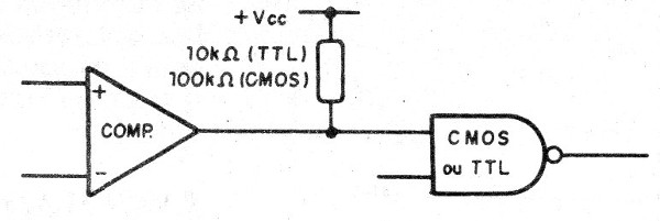
This resistor is required because the comparator output usually consists of a transistor with the collector off (open).
Without an external resistor, the transistor is not polarized.
Applications
Here are some important applications whose basic component values ??can be left open, as they depend on the desired behavior for the circuit.
Light alarm
In Figure 9, we have the basic circuit for triggering an alarm system with a cut or the incidence of light, based on a comparator.
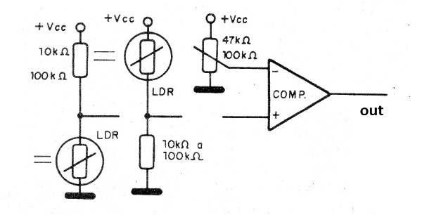
The loads may be one of the circuits shown in Figure 7, and the sensitivity or trigger point is adjusted by varying the reference voltage through a potentiometer.
This circuit has as its main characteristic the speed of response since, with minimal light variation from the setpoint, it triggers. The sensors can be LDRs (Light Depend Resistor or even photoresistor with increased resistor heat.
Temperature Alarm
By using thermistors NTC (Negative Temperature Coefficient) or PTCs (Positive Temperature Coefficient) as sensors, we can control a load with slight temperature variations using the configuration on sensitive thermostats. In Figure 10, we show how to do this.
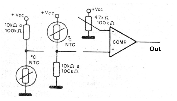
The circuit trigger point is set on the potentiometer.
Window Comparator
Two voltage comparators connected as shown in Figure 11 form a configuration called a window comparator. This configuration is due to the fact that in the graph which represents the behavior of this circuit, shown in Figure 12, we have a “window” where the output goes to high or low level (Vcc or 0V), determined by the relationship between the reference resistor or reference voltage values.
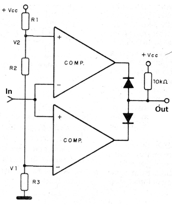
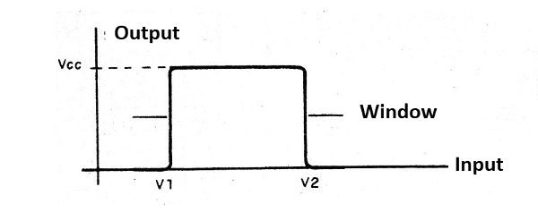
Thus, for the indicated circuit, the load will be triggered only when the input voltage is in the range of V1 to V2. Below V1 and above V2 the load will be disabled.
If we connect an LDR at the input of this circuit, as shown in Figure 13, and adjust potentiometers P1 and P2 so that the output remains off with normal lighting, any disturbance of ambient lighting, increasing or decreasing in intensity, will cause the system to trigger.
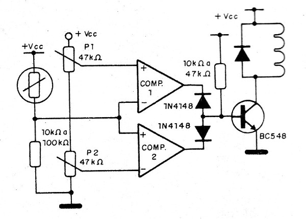
Instead of LDR, we can use other types of sensors in this circuit like NTCs PTCs, pressure, position, etc.
Phase Comparator
Several comparators connected to a series resistor network capable of providing phase reference voltages, as shown in Figure 14, allow the elaboration of a phase comparator.
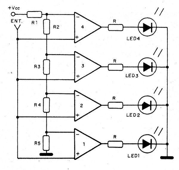
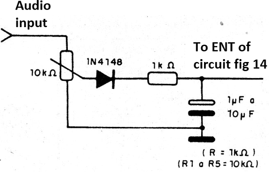
We can use this circuit in a VU (Volume Unit) meter by adding the audio input shown in Figure 15.
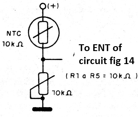
In order for us to have a phase thermometer, we can turn on the input circuit shown in Figure 16.
Oscillator
A voltage comparator can also be used to oscillate and thereby generate signals in a range of up to a few hundred kHz. The configuration for this purpose is shown in Figure 17.
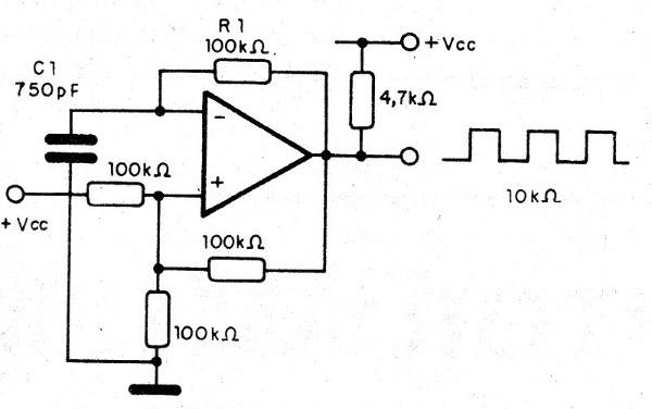
The Capacitor C1 and resistor R1 determine the operating frequency of the oscillator (see Mathematics For Electronics section how to calculate the frequency). Other configurations can be obtained to generate different waveforms.
We can also use the comparator as an amplifier, but this will not be covered in this article. We will now look at some types of comparators you can make projects nowadays.
The Comparator in Practice
In principle, any operational amplifier can be used as a comparator.
So, if we only need one comparator in a project, we can use the 741 operational amplifier, no problem.
In figure 18, we have the casing and the pinout of the operational amplifier 741.
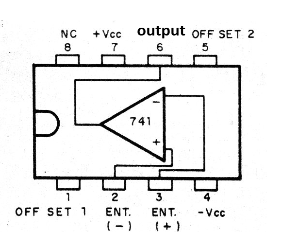
The main characteristics of this operating are:
Maximum voltage: 18 + 18 V
Input Resistance: 2M ohm
Typical gain: 300,000
Output Resistance: 75 ohm
Maximum output current: 25 mA (typ)
A common series of comparators is LM293, 393 and LM2903 whose pinouts are shown in Figure 19.

The characteristics of these amplifiers are as follows:
Supply voltage range: 2 to 36 V (18 + 18 V)
Gain: 200 V / mV (typ)
Another popular family is the LM139, 239, 339 and LM290, shown in Figure 20.
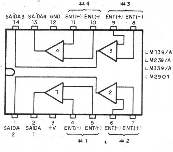
In one casing, we have four comparators that can operate with voltages from 1 to 18 V and have gains from 100 000 to 200 000 depending on the type.
The maximum output current is 16 mA and it typically requires a 2k2 pull-up resistor.
Conclusion
There is no limit to what you can do with a voltage comparator. On our site, we have a multitude of projects that use these components. Browse both the articles and our huge circuit bank by typing, for example, LM339 in the search.


