Translated into English by Patricia Lima Carlos.
Obs. This version of the article is from 1982, but still very current (2017), since it can be easily implemented by the technologies it uses and deals with a subject explored in other articles in this section.
It is a device for you to hear and record the mysterious sounds that are carried by the induced currents on the earth, some of which can start several speculations. The sensitive device we describe will allow the reader to hear these sounds and even record them.
Some reports and even books have addressed the interesting subject of capturing strange voices and mysterious sounds, from out-of-sync radios, adapted recorders and many other common electronic devices.
The authors seek to give the most diverse interpretations for the sounds captured, speaking about spirits, ghosts, beings, extraterrestrials and even in recordings “from the past”.
These sounds really exist, that is, they can manifest themselves under various conditions, as we shall try to explain in this article, although we are not always in agreement with the explanations that are given to their origins.
The sensitive electronic circuits of radios, recorders, amplifiers, etc., can pick up noises and even sounds that otherwise could not be detected, and by their very nature can reinforce these sounds or deform them to the point of emphasize, modifying or even distorting our perception.
The origins of these sounds may be as diverse as, for example, radio stations, communications stations, various interferences of electronic equipment and even those that have no plausible explanations.
Hearing these sounds, including the mysterious ones, is what we propose to the reader in this article, opening up a new and interesting field of research.
The apparatus we describe is nothing more than a sensitive amplifier, which is adapted to capture a special type of signal: that which is induced on the earth and which can bring a thousand and one different information from the most diverse origins.
Listen to the sounds of Earth, as mysterious as interesting; Hearing voices or strange noises; Listening to voices of the past or extraterrestrial beings, as some want, is what we propose to the reader with this interesting device. Fully portable 'and battery operated, it can be taken to places free of interference and coupled to common recorders.
HOW IT WORKS
The soil with its dissolved minerals in its unit and many other substances is an excellent conductor of electricity. Thus, energy distribution companies take advantage of it as a second conductor, in order to economize wires, as suggested in Figure 1.
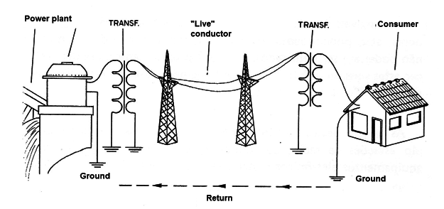
These companies then connect one of the energy conductors to the earth itself, which conducts electricity as well as any other conductor, if not better.
In addition to conducting electricity from power plants and distribution companies, the soil is also driven by other types of current. They are the currents coming from electric discharges, induced by magnetic fields, like the one of the earth itself, and also many chains that are discharged by diverse types of electrical appliances (Figure 2).
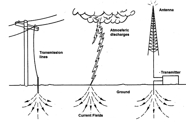
Radio transmitting stations, for example, connect one of the poles of their antennas to the earth, as this can conduct the waves as well as the air itself or vacuum; Factories and workshops link motors and other grounding machines, both to divert dangerous currents to it and to divert the interference they may cause on nearby radio equipment.
Finally, if we can make an analysis of what we find on the earth, we will see an infinite number of current types of different frequencies and origins, circulating in the most diverse directions.
Of course, besides the currents we have analyzed, there are others that are not well explained and sometimes can be heard in the form of strange sounds or noises, and in some cases even voices!
In order to "pick up" these currents, all we have to do is stick two metal electrodes (two rods or plates) in the ground in such a way that, by the direction of the flow of the current induced in the ground, between them it manifests a potential difference. Figure 3 gives an idea of ??the positions of these plates, so that signals are captured.
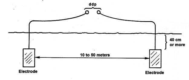
The potential difference found between the plates, which corresponds to the signal, has the same characteristics of this signal, ie, intensity, frequency, phase, etc. In order for us to perceive these currents, we need to "translate" them in terms of our senses.
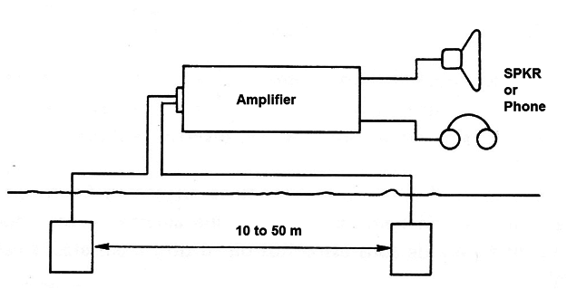
One way to do this is to amplify these currents with the help of a good amplifier, as shown in Figure 4, and apply them to a headphone or loudspeaker. The currents whose frequencies are between 16 Hz and 20 000 Hz (vibrations per second) and which correspond to the audible sounds, will become sounds and we can hear them.
Even if the existing currents have higher frequencies, if they are "modulated" we can work them to extract the audible information they have. This is the case of radio signals of much higher frequencies (100,000 Hz or more), which are modulated and therefore can carry the voice, music and other sounds.
To extract the modulation, all we need is a detector diode, as shown in Figure 5.
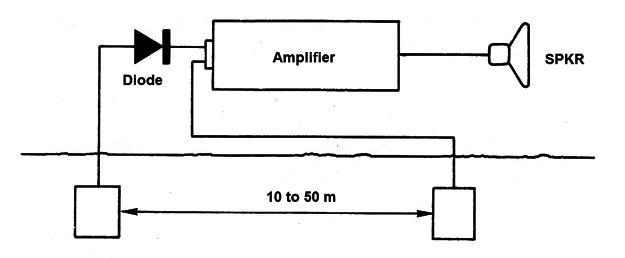
In short, whether using a simple amplifier or an amplifier with a detector, we can "hear" signals of all kinds on the ground, which is the basis of our design.
We then use a sensitive integrated amplifier, which can magnify thousands of times the currents picked up by the electrodes and apply them to a speaker or headset.
At the input of this amplifier we will have both the direct connection of the electrodes, to hear signals of low frequencies, as well as of a diode, to hear the signals of high frequencies.
The handset is powered by two or four small batteries and can also be attached to a standard portable recorder.
Its assembly is relatively simple not offering difficulties to the amateur. All components are common and can be found in specialized houses at a very affordable cost.
MATERIAL
The material used at the assembly does not influence either in the appearance of the device or its performance. Thus, we suggest to the box the use of a shoulder strap system according to Figure 6, facilitating its use in field.
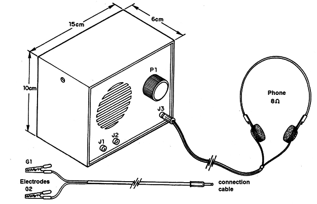
A box can be made of plastic, metal or any other material, dimensions of approximately 15 x 10 x 6 cm.
Electronic components can be achieved without too much difficulty. The reader should start with the printed circuit board, which must be carefully designed. For this you need to have the minimum resources, which is a printed circuit board, a blank board, a corrosive solution and finally a manual or electric drill, with a drill bit between 0.8 and 1 mm.
The integrated circuit is a TBA820S, which consists of a complete amplifier. Only this integrated should be used. For more safety at the assembly, when the reader purchases the integrated circuit he/she can also order a 14-pin DIL holder for it. The use of the holder facilitates the exchange of the integrated circuit in case of problems and also prevents heat from affecting it during an assembly.
The diode rectifier D1 of general use, can be of all type of germanium like 1N34, 1N60, etc.
For the speaker it is possible to use a unit of 8 Ω x 5 cm, as found in portable radios, or if the reader wants - greater fidelity of reproduction, a loudspeaker greater than 8 Ω x 10 cm. In this case, a box should be a little larger to accommodate it.
The P1 potentiometer serves as the sensitivity or volume control for the amplifier. This potentiometer has the general switch 31, which switches the appliance on and off. Its normal value is 100k, but other values ??are also used, such as 47k or even 220k.
We have two types of capacitors in the assembly. The so-called “small” by their values and which are the depolarized, which in the scheme and in the list are expressed in nF (nanofarads) and pF (picofarads) and the" big" ones that are the polarized, which are expressed in µF (microfarads).
The depolarized can be both ceramic and metallized polyester, while the large ones are electrolytic for a working voltage of at least 6 V.
The resistors are all 1/8 W, with the values indicated on the list.
Resistors of larger size, ie, 1/4 or even ½ W can be used in the absence of the originals, provided the values are kept in Ω.
The battery that feeds the circuit is made up of 4 small alkaline batteries, so there should be an appropriate holder.
We finally have 3 jacks, two being of input to the earth signals and one output for an eventual connection of a headset.
The output jack is a "closed circuit" type with 3 terminals. This jack allows the headphones to turn off automatically at the time the loudspeaker is switched on, it is the same type found on portable radios to connect the headset.
Low-impedance headphones, such as those found in portable radios and recorders, or even high-fidelity padded ones, can be used.
Complementing the material there are the wires, welder, potentiometer switch and cable with plug according to J1 and J2 jacks to connect to the grounded electrodes.
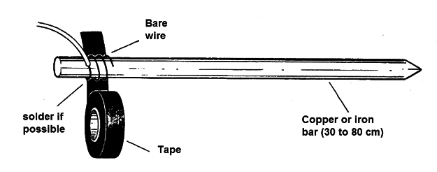
The electrodes consist simply of metal bars of at least 40 cm in length, with sharp tips to be buried. In each bar there must be a coated wire with a length of at least 10 m to connect the amplifier. Figure 7 shows how to make these bars and how to connect the wires, ensuring good contact.
As an integrated circuit is used, and the arrangement of its terminals does not favor the assembly of the bridge, we chose the printed circuit board assembly. As we have already warned in obtaining the material, the reader must have the resources for the elaboration of this board. In Figure 8 we give the normal-size printed circuit board design, both on the component side and the copper side.
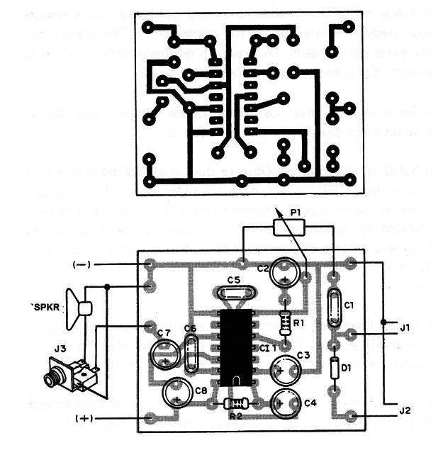
The complete diagram of the apparatus is shown in Figure 9, where the components are represented by their symbols. The reader should try to "interpret" this diagram, becoming familiar with the symbols used.
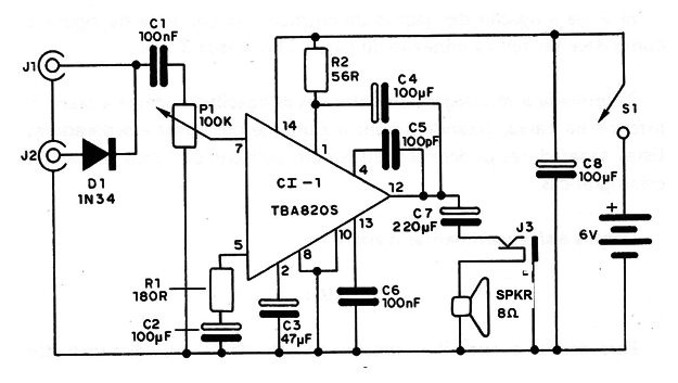
The sequence of operations for perfect assembly is as follows:
A) Start by welding the integrated circuit or its bracket. Snap the pins so that they exit through the copper side. Then weld one by one, taking care that there is no weld scattering that can "stick" to the adjacent pins. If this happens, wipe the excess weld with the welder's own tip and a stick.
If you directly weld the integrated circuit, note its position that is given by the mark identifying pin 1.
B) Weld the diode D1 observing its polarity or the arrangement of its internal elements, if it is transparent. Be quick in welding this component. The jacks, potentiometer, speaker, and battery holder must be attached to the box.
C) Weld the resistors. The values of these components are given by the colored bands. See the material list.
D) Weld the capacitors. Note that the electrolytes have the right position for placement, that is, we should look at the side marked with an H in their casing. The other capacitors are not polarized, but must be welded quickly because they are sensitive to heat.
View their values according to the material list. The capacitors C1 and CE may come with markings such as 104 or .1 or even 0.1 ?F.
E) Connect the potentiometer using ordinary plastic sheath wires. These wires should be short and straight. See the wire connection order so that the control does not work "upside down".
F) Connect the battery holder and S1. See the polarity of the wire that goes from the holder to the switch, which is positive. This wire is red.
G) Connect the input and output jacks. See Figure 8 for how to connect the 3-wire J3 jack.
After the assembly is completed and the connections are checked, insert the board into the housing and fasten it with screws and spacers.
These spacers can be made from pieces of ballpoint pen tubes.
Then just try the device.
TEST
To test the appliance, connect the input J1 to the plug with two pieces of wire with alligator clips at the ends (Figure 10).
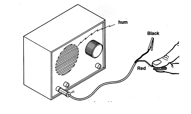
After turning on the appliance, by pressing S1 on the potentiometer, and opening the volume, touch with your fingers the red entrance claw. The loudspeaker should emit a severe snoring or hum.
If nothing happens, check the assembly and check the condition of the batteries.
If everything happens as expected, just think about using the device in your researches.
Prepare the electrodes for this.
WHAT YOU WILL HEAR
Preferably the electrodes should be connected in open field, spaced apart from each other by at least 15 m, and away from poles, transmission lines or electrical installations (Figure 11).
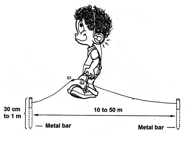
Once the device is switched on, first try input J1, without the diode. If you hear nothing unusual, try input J2.
The serious buzzing that is heard, similar to what happened in the test, comes from the induction of 6oHz of the electrical current of the power grid. If it is too strong, look for an isolated location away from transmission lines that may be interfering.
The sounds that can be heard on the speaker or handset are likely to have the following sources:
A) Nearby radio stations (few kilometers).
(B) Low frequency (10 kHz to 200 kHz) communications stations, such as airports or navigation services (voices or telegraph signals).
C) Atmospheric electrical discharges (clicks, buzzing or buzzing of various natures).
D) Apparatus other than sound or other types (sounds or music), at small distances.
E) Industrial machines (up to a few kilometers).
F) Sounds of unknown origins (various types such as squeaks, voices, noises, etc.) - these are of particular interest to the researcher!
To record the sounds, simply connect the output J3 to the recorder.
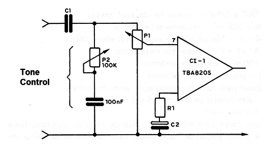
In Figure 12 we show an optional tone control.
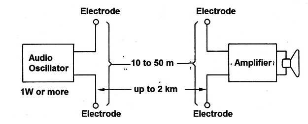
Note: In one of our books (not available in English by now) we describe an interesting telegraphic transceiver, in which the signals were sent through the earth. This device can act as a sensitive receiver for that system, greatly increasing its range, which can reach up to a few kilometers. The transmitter consists of a grounded oscillator, and the receiver a headphone, as shown in Figure 13.
Cl-1 - TBA820S - integrated circuit (audio amplifier)
D1-1N34, 1N60 or any germanium diode
P1 - 100 k with switch - potentiometer
R1 - 180 R x 1/8 W - resistor (brown, gray, brown)
R2 - 56 R x 1/8 W - resistor (green, blue, black)
C1, C6 - 100 nF - ceramic capacitors
C2, C4, C8 - 100 µF x 6 V - electrolytic capacitors
C3 - 47 µF x 6 V - electrolytic capacitor
C5 - 100 pF - ceramic capacitor
J1, J2 - simple miniature jacks
J3 - "closed loop" earphone jack
FTE - 8 ohm speaker x 5 cm
B1 - 4 alkaline batteries - 6 V
Miscellaneous:
an assembly box, printed circuit board, holder for 4 small batteries, wires, welding, low impedance earphone, potentiometer button, etc.


