
What we have is a fairly sensitive indicator of thermal variation which can be used in field research.
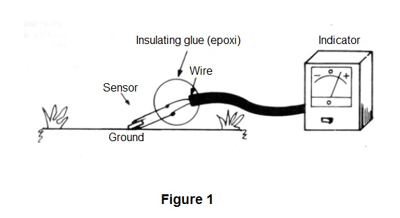
In Figure 1, we have the way to use the sensor in the verification of a heating (perhaps by the presence of radioactive material) in a place of landing of a UFO.
The circuit runs on batteries and its durability is very long since the consumption is very low.
Another possibility of use for this apparatus is the verification of temperature variations in objects or devices that have undergone unknown influences of the passage of a UFO and that present some type of suspicious behavior.
How it works
In Figure 2, we have the complete diagram of the temperature variation detector.
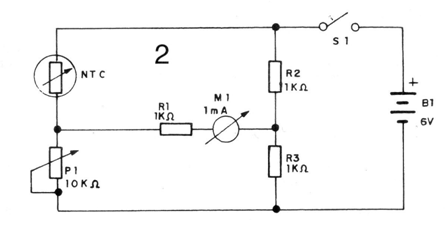
The circuit basically consists of a Wheatstone bridge in which in one of the branches we put a sensor and in the middle an indicating instrument.
By zeroing the instrument at room temperature, when a temperature change occurs on the sensor, the indicating instrument will demonstrate this with the movement of its needle.
The shift of the pointer to the right indicates an increase in the temperature in place with respect to the environment and a shift to the left indicates a drop in temperature.
The greater the deviation of the instrument needle, the greater the temperature variation.
An important point to consider in this type of device is the so-called sensor readiness. It takes some time for the sensor to reach the temperature of the location, which means the searcher must wait a bit to check whether the pointer moves or not.
This waiting time will depend on the size of the sensor, and can range from 30 seconds to a few minutes, typically.
Assembly
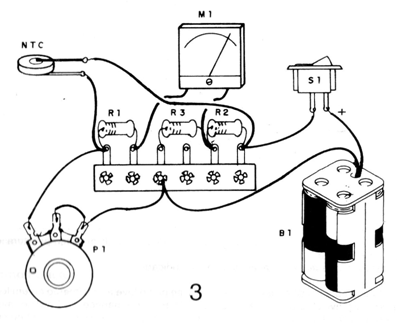
In Figure 3, we have the assembly aspect. As it is a very simple circuit you will not need to use a printed circuit board. The main components are welded on a terminal bridge.
The indicating instrument can be either a milliammeter from 0 to 1 mA or a zero-sensitive microammeter in the center, such as those used to indicate the state of the battery in many electronic devices.
In fact, the reader can save a lot of money by taking advantage of this instrument from some out-of-use device.
The resistors are 1/8 W or larger and suitable batteries must be used.
The NTC can be of any type with values ??between 5 k ohms and 100 k ohms. The important thing is that the adjustment potentiometer has the same order of value of the NTC resistance at room temperature.
Many older TVs use NTCs to control their circuitry as a function of temperature. Luckily, the reader can get an NTC for free on one of those out-of-use devices.
Another possibility for those who wish to have an extremely sensitive circuit in the detection of temperature variations is to use a thermometric NTC, which has the appearance shown in Figure 4.
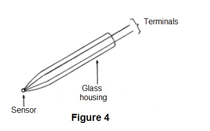
This sensor has a very large readiness and its thermal capacity, being very small, allows us to detect variations of temperature in very small objects by the simple contact.
Test and Use
To test the device, simply turn on its power at S1 and adjust P1 until the indicating instrument needle goes to the center of the scale.
Then, holding the sensor between your fingers, the needle must move, indicating a rise in temperature.
If the null adjustment is not achieved, ie, the needle does not go to the center of the scale, either you change the potentiometer to a higher value or exchange R3 for a higher value resistor.
To use, the procedure is as follows:
a) Switch on the power supply by pressing S1
b) Adjust P1 until the needle of the instrument goes to the center of the scale:
c) Position the sensor where you want to check the temperature in relation to the environment;
d) Observe the movement of the indicator needle.
In a field survey, keep in mind that the slight heating of a site may be indicative of the presence of radioactivity. Avoid staying in the room for a long time if this type of indication occurs, until it can be verified with a radiation meter.
Resistors (1/8 W, 5%)
R1, R2 and R3 - 1k ohms - (brown, black, red)
P1 - 10 k ohms - potentiometer
NTC - thermistor or resistor with negative temperature coefficient from 5 k ohms to 100 k ohms - see text
Miscellaneous
M1 - 1 mA - milliammeter - see text
S1 - single switch
B1 - 6 V - 4 small batteries
Housing for mounting, battery holder, terminal bridge, wires, welding, etc.


