Very low value resistors
In some assemblies resistors of less than 1 ohm values may be required, which may mean difficult work to obtain. One simple way to obtain resistors of values less than 1 ohms is by associating resistors of this value in parallel. Thus, as shown in Figure 1 we can obtain resistors of 0.5 (0.47), 0.3 (0.33), 0.25 (0.22), 0.2 and 0.1 ohms by connecting a certain number of 1 ohm resistors in parallel.
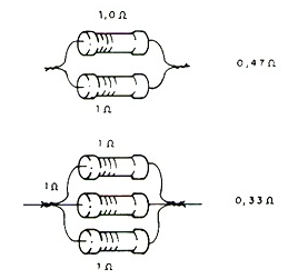
The value of the final resistance is obtained by dividing 1 by the number of resistors that are connected in parallel. We can also use the formula:
1 / R = 1 / R1 + 1 / R2 + .... 1 / Rn
By this formula, using R1, R2, R3, etc. = 1 ohm, by fixing R we can get Rn to have the desired resistance. The power that the set can dissipate will be given by the current in each resistor multiplied by the voltage to which the set is subjected. In the simplest case of equal resistors in parallel, the total power will be the sum of the resistor powers.
Measuring enameled wire thickness
Very thin wires cannot be easily measured without the help of a micrometer or even a caliper. However, there is a simple method of determining the thickness of an enameled wire without the need for a precision instrument capable of working with very small diameters.
A simple ruler can be used in this case. The idea is to wrap a known number of turns of the wire side by side in a pencil and measure the total length of the coil obtained, as shown in Figure 2.
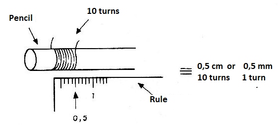
Dividing the length of the coil by the number of turns will have the thickness of a loop ie the diameter of the thread. For example if 10 turns result in a length of 5 mm the wire thickness is 0.5 mm. If the wire is too thin, wind enough turns to get an accurate measurement, at least about 5 mm. For the correspondence in mm with the AWG number of the wire use the table given this link https://en.wikipedia.org/wiki/American_wire_gauge .
Non polarized capacitors
Electrolytic capacitors are polarized components, ie they have armatures that must be connected to the positive and other to the negative of the supply. If these components are inverted they risk shorting or not yet having the expected capacitance.
However, electrolytes are the economical solution for obtaining large capacitance values. What to do if we need an electrolytic capacitor that can be connected to AC? There are two solutions to this which are shown in figure 3.
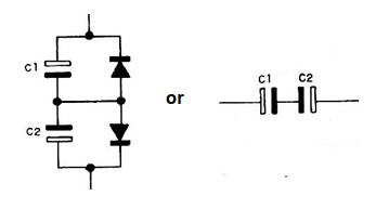
The first makes use of two diodes that are wired to prevent the capacitors from applying voltage that does not correspond to the right polarity. The second is simpler and simply consists of connecting capacitors in opposition.
Of course, in this case, to get 10 uF we need two 22 uF capacitors, but the effect obtained is the desired one.
10 M ohms resistor
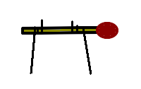
A 10 M ohm resistance or so (very high values) can be obtained with a common matchstick, as shown in Figure 4. This is the resistance of the wood, which will vary according to its degree of humidity.
Very low value homemade capacitor
Two twisted wires, but not connected together, form a very low value capacitor. This technique allows capacitors with values below 10 pF to be obtained, as shown in figure 5.
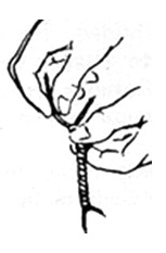
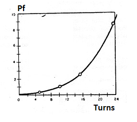
In the graph of figure 6 we see the capacitance values obtained for various braided wire lengths. One idea is to use thin solid wire, like those employed in telephone connections. But note that unused ends should remain off.
