Insoles and pillows with magnets, applicators which generate static or variable magnetic fields with frequencies between a few hertz
up to a few kilohertz, bracelets with magnets and many others, are devices that we find in stores that work with alternative therapies.
Although the beneficial effects of such fields have not been proved by science yet, there is no record of them doing harm to the intensities with which they are used in different cases.
If the readers want to have an applicator for experimental purposes or even because they have felt some beneficial effect with previous application (even if it is psychological), we give in this article a simple and quite efficient project.
It is a generator of magnetic fields in two frequency ranges: between 1 Hz and 20 Hz and between 50 Hz and 1 000 Hz.
Powered by common batteries, it has power on the order of 1 W and is totally shockproof.
Two low-cost integrated circuits are used and its assembly is not difficult for the readers.
Characteristics:
Supply voltage: 6 V
Maximum current: 300 mA (tip.)
Output Power: 1 W (tip.)
Frequency bands: 1 Hz to 20 Hz and 50 Hz to 1 000 Hz
HOW IT WORKS
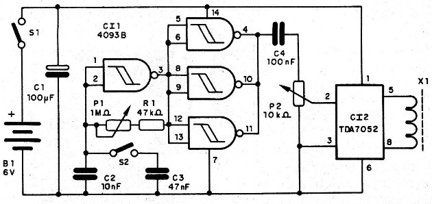
The signals of the frequencies to be produced by the magnetic fields are generated by an oscillator based on one of the ports of the integrated circuit 4093.
In this circuit the connected capacitor (C2 or C3) determines the frequency range, while P1 makes its fine adjustment.
The signal generated by this oscillator is rectangular and is then applied to three other ports of the same integrated which works as inverter buffers.
We have at the exit of this port a signal of good intensity which drives via P1, an integrated amplifier of the type TDA7052.
At the output of this amplifier, which with only 6 V, develops a power of 1 W.
This signal is then taken to an application coil which can have the most various formats according to the readers’ will.
ASSEMBLY
In Figure 1 we have the complete diagram of the applicator.

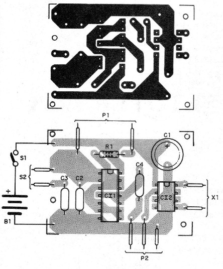
The arrangement of the components based on a printed circuit board is shown in Figure 2.

The resistors are 1/8 W with 5% or more, and the capacitors are ceramic or polyester, except C1 which is an electrolytic of non-critical value, with a working voltage from 6 V.
P1 and P2 are common potentiometers.
The batteries are installed in holders and S1 can be coupled to the P2 potentiometer of the intensity control.
S2 is a 1-pole x 2-way switch used to select the operating ranges of the appliance.
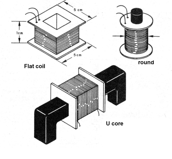
The coil X1 is formed by at least 150 turns of 28 wire which may have one of the formats shown in Figure 3.

The format chosen will depend on the desired application, for example to run on the skin, to insert a finger or hand etc.
TEST AND USE
Magnetic fields, in principle, cannot be perceived by our senses, so we need special resources to notice them.
A simple way is to approach the coil with a medium-wave radio tuned out of stations.
The coil acts as a "signal gun" and its field can be heard on the speaker.
The adjustment for use will depend on the application we have in mind: with S2 closed we have lower frequencies and with it open we have higher frequencies.
P1 adjusts the frequency of each range and P2 the intensity of the field.
Semiconductors:
Cl1 - 40938 - CMOS integrated circuit
Cl2 - TDA7052 - integrated circuit amplifier
Resistors (1/8 W, 5%):
R1 - 47 k ohm
P1 - 1 M ohm - potentiometer
P2 - 10 k ohm - potentiometer
Capacitors:
C1 - 100 uF x 6 V - electrolytic
C2-10 nF - ceramic or polyester
C3-47 nF - ceramic or polyester
C4 - 100 nF - ceramic or polyester
Miscellaneous:
B1 - 6 V - 4 small or medium size batteries
S1 - single switch
S2 - single switch or 1-pole switch x 2 positions
X1 - Applicator coil - see text
Printed circuit board, battery holder, assembly box, potentiometer buttons, coil form, wires, welding, etc.


