Obs. This project waspublished in a brazilian magazine and translated into English to be part of the book Bionics for the Evil Genius (TAB 2006).
In this project, the subject will touch the electrodes with his or her fingers, controlling the pressure of contact in order to make the circuit generate a tone with a desired pitch or to cancel a tone produced by the circuit.
Any change to the pressure exerted on the electrodes will make the oscillator alter its frequency.
Thus, the subject can vary the tone pitch, controlling the strength of the electrodes in this biofeedback process.
Biofeedback means that the control of an electronic circuit is made by a loop that includes the subject’s body, which could be a human being’s body. It is a biologic or bio loop, carrying the control signal back to the input.
How it Works
The circuit has the same configuration as in the previous project. It is formed by two audio oscillators, and each one of them is made from one of the four gates of a 4093 complementary metal oxide semiconductor (CMOS) integrated circuit (IC). The 4093 consists of four NAND two-input Schmitt gates that can be used in their original function or as inverters or digital buffers.
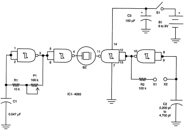
The first oscillator operates at a frequency determined by C1 and adjusted by P1, and it drives a piezoelectric transducer (BZ) Via the digital buffer formed by one of the four gates at the IC.
The second oscillator operates at a frequency determined by C2 and the body of the subject, which is pressing on the electrodes. As the amount of pressure on the electrodes changes, so does the resistance and the frequency generated by the oscillator, as we have explained previously.
This second oscillator also drives the same output transducer via a digital buffer formed by one of the four gates in the 4093 1C.
If the frequencies of the generated signals are the same, no sound is produced by the transducer (beat zero), because the signals are canceled. This is the point of balance or zero point of the subject, and it can be reached by controlling the amount of pressure on the electrodes.
In Figure 1, we have the schematic diagram of the audio biofeedback.

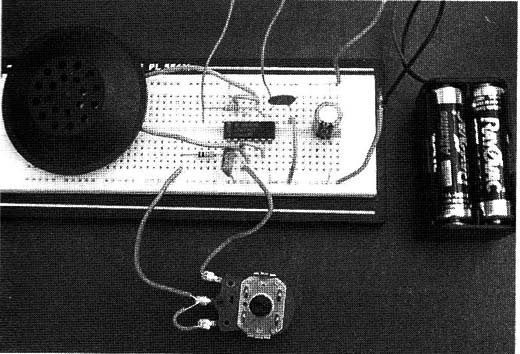
The experimental version can be mounted on a solderless board, as shown in Figure 2.

The circuit is powered from four AA cells or a 9-volt battery. The electrodes are made with two metal rods as in the previous project on visual biofeedback. (BM007E) Do not use a transformerless power supply.
The transducer BZ is any piezoelectric type or a piezoelectric tweeter without the internal transformer that should be removed.
The circuit can easily be housed in a small plastic box with two pieces of wire, 30 or more inches long, that are connected to the electrodes via X1 and X2.
X1 and X2 are optional as you can wire the electrodes directly to the circuit or use terminals.
IC1- 4093 CMOS integrated circuit, four Schmitt NAND gates
R1-10 k Ω x 1/8 W resistor, brown, black, orange
R2 - 100 k Ω x 1/8 W resistor, brown, black, yellow
P1- 100 k Ω, potentiometer, lin or log
C1- 0.047 µF ceramic or metal film capacitor
C2- 2,200 to 4,700 pF ceramic capacitor
C3 - 100 µF x 12 V electrolytic capacitor
S1- Single pole, single throw (SPST) toggle or slide switch (on/off switch)
B1- 6 to 9 V AA cells or battery
BZ: Piezoelectric transducer (see text)


