Obs. This article is part of my book Bionics for the Evil Genius (TAB - 2006) and was originally published in portuguese in a Brazilian Magazine.
The reader can observe what happens with plants or other living beings, such as insects or even small mammals, when exposed to external influences such as electric fields, magnetic fields, or light of different wavelengths (colars).
Experiments can induce changes in the animal or plant’s behavior, and what is discovered can be used to create new bionic devices.
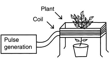
What we are proposing here is to mount a magetic field generator for this kind of experiment. The circuit will generate high-current pulses that, flowing across a coil, will create a pulsed magnetic field. Fig. 1 shows how the coil can be placed around a plant. applying the field to it.

The coil can be placed around cages of insects or other animals according to the experiment to be performed. The magnetic field can also be used to excite plants to grow faster or to produce larger fruit. We suggest experiments with tomato plants, which are easy to cultivate and observe.
In the project described here, the field strength can be controlled by a large range of values and also by the frequency. In special experiments with low-frequency fields, caution must be taken. The fields created by the low-frequency power lines are dangerous, causing cancer and other problems, and studies with plants and other living beings confirm this.
Bionic Experiments and Projects
Many experiments and applications can be suggested based on this circuit:
Study how circadian rhythms change when magnetic fields are applied to plants or insects.
Conduct research to see how fruit develops under the influence of magnetic fields.
Determine if magnetic fields can cause a change in the behavior of insects such as ants or bees.
See how magnetic fields can influence the behavior of small aquarium fish.
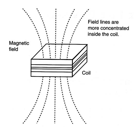
It is important to know that the low-frequency fields produced by the device are very weak and are not harmful for humans, because they are concentrated only inside the coil where it is more intense, as shown in Figure 2.

Otherwise, the device’s strength is many times lower than the low-frequency magnetic fields produced by domestic appliances such as electric razors or appliances with motors that are much more dangerous.
How It Works
The basic project consists of a relaxation oscillator plugged into the AC power line that has a silicon controlled rectifier (SCR) as its main component. Figure 3 shows the block diagram for this circuit.

The AC power line voltage is rectified by D1, charging the capacitor C1 through R1, with the peak value of this voltage at about 150 volts in the 117 VAC power line. The SCR, P1, R2, and C2 form a relaxation oscillator with a neon lamp. A coil wired in series with the anode of the SCR is the load.
This circuit works as follows: The capacitor C2 charges across the potentiometer P1 and R1 until the trigger voltage of the neon lamp is reached. This voltage is about 80 volts for common neon lamps, as recommended by the NE-2H for this circuit.
When the neon lamp is triggered, the capacitor C2 discharges to the gate of the SCR, triggering this component to the on state. In the on state, the SCR, C1, and the coil form a closed circuit. The capacitor C2 then discharges through the SCR, producing a powerful current pulse in the coil. This pulse produces the magnetic field for the experiment. As long as the voltage in C1 falls below the holding value, the SCR triggers off and a new charging cycle begins.
Triggering on and off, the relaxation oscillator produces high-power magnetic pulses in the coil. The strength of the pulses and the frequency depend on several factors, such as the following:
The value of Cl determines the intensity of magnetic pulses; capacitors with a range between 1 and 32 ,uF can be used. This component also determines the frequency. Larger capacitors will produce stronger pulses, but the frequency is lower.
The value of C2 and any adjustments to P1 determine the frequency.
The number of turns of the coil determines how strong the magnetic field is.
Playing with these three parameters, the reader can create a version customized to the experiments or applications he or she has in mind.
How to Build
Figure 4 shows the schematic diagram for the magnet field generator.

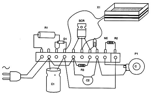
The simplest way to mount this circuit is to use a terminal strip to fit the components, as shown in Figure 5.

Of course, if the reader has the resources, he or she can mount the project using a printed circuit board (PCB).
The capacitor C1 is a high-Voltage polyester orI electrolytic type. If an electrolytic capacitor is used, the position must be observed because it is a polarized component.
The minimum voltage for this component is given in the parts list. C2 is any polyester capacitor rated to 100 volts or more. R1 is a wire-wound resistor, and the values indicated between the brackets are for the 220/240-volt AC power line.
The coil is formed by 50 to 500 turns of any wire in a box that fits the assembly. You can use enameled wire (AWG) from 22 to 32 or common plastic wire of any gauge.
Testing and Using
Plug the power cord into the AC power line. Adjusting P1, the neon lamp will flash. The flash rate depends on the value of C1 and the adjustment of P1.
The experiment is then conducted, placing the specimens inside the coil.
Decide what the time frame will be and what you are intending to observe.
Use additional resources to measure the changes in the specimcn’s behavior, such as a thermometer.
SCR: TIC106 (D) SCR
D1: 1N4004 (7) silicon rectifier diode
NE: Neon lamp, NE-2H or equivalent
R1: 1 k ohm x 10 W (2.2 k ohm) wire-wound resistor
R2: 10 k ohm x 1/8 W resistor, brown, black, orange
R3: 47 k ohm x 1/8 W resistor, yellow, violet, orange
P1: 1 M ohm lin or log - potentiometer
C1: 1 to 32 µF x 200 V (400 V) polyester or electrolytic capacitor (see text)
C2: 0.1 µF x 100 V - polyester capacitor
X1: Coil (see text)
Other Parts: Terminal strip or PCB, power cord, wires, box, etc.


