One of the most curious interactions between an external source of energy and a living being is one that causes the living being to undergo a hypnotic state.
Not only humans, but many animals, can be hypnotized. In this state, they lose control of their movement and can even be subject to commands that, in normal conditions, they would not respond to.
Many techniques exist for hypnotizing a living thing, including humans. The simplest form, which is used by many, utilizes the continuous movement of a pendulum or repetitive sounds such as phrases, instrumental music, or fixed-frequency sounds. If the hypnosis uses an electronic device or interaction between a living being and an electronic device occurs, we can categorize this technique as a bionic process.
Such a hypnotic process is just what we are going to describe now: a project in which a living being (including a human) is put in a relaxed, hypnotic state. Such a frame of mind would be akin to the intermediate state between being awake and asleep, such as the “alpha” state used in transcendental meditation and other Eastern practices.
Of course, the device described here is not recommended for use with people without specialized aid.
The states experienced during the hypnotic processes can be dangerous, but you can conduct some interesting experiments using mammals, insects, fish, and other creatures, without causing them any harm or risk.
The following experiments are suggested:
Study the influence of pulsed light on a plant’s growth.
Conduct research on the influence of intermittent light on the behavior of insects.
Study the stress of hens and other birds under the influence of blinking light-emitting diodes (LEDs).
Study the influence of blinking LEDs on peopleªs ability to concentrate or their stress levels.
How it works
The basic circuit proposed here consists of a low frequency oscillator that drives two high-power LEDs. As shown in Figure 1, the LEDs will blink at alternating times.
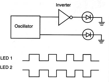
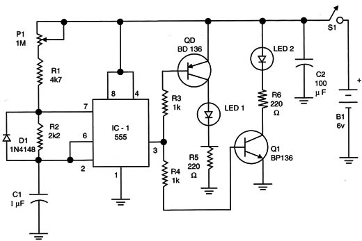
The core of this circuit is the 555 integrated circuit (IC) wired as an astable multivibrator. The frequency of the light pulses is determined by P1.
The diodes are used to produce a signal with 50 percent of the duty cycle. This is necessary because the LEDs of each channel must be on the same time interval.
The signal at the output of the 555 is applied to two complementary transistors that have as a load high-power LEDs, or small incandescent lamps if the reader prefers.
The negative positive negative (N PN) transistor becomes active when the output of the 555 reaches the high logic level, and the positive negatiVe positive (PNP) transistor begins when the output is at the low logic level.
As for the values used in the project, the LEDs will blink at frequencies between 0.1 and 10 Hz approximately. Of course, the reader can change C1 to alter this range of frequency according to the experiment in mind, and smaller values for C1 increase the frequency.
The transistors recommended can drive LEDs or lamps with currents up to 500 milliamps. Small 6-volt incandescent lamps can replace the LEDs, depending on the experiment.
The LEDs can be the same or different colors. It is also possible to use only one LED, keeping the other channel off. The circuit is powered from 4 AA cells or a power supply using 6 V x 500 milliamps.
How to Build
Figure 2. shows the schematic diagram for the hypnotic LEDs.
The circuit can be mounted using a small printed circuit board (PCB), such as the one shown in Figure 3.
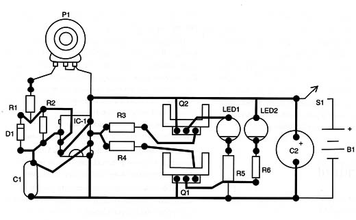
When mounting, the reader must take care when positioning the polarized components such as the IC, the electrolytic capacitors, the LEDs, and the transistors. If the circuit is used to control light sources larger than 100 milliamps, a heatsink will be needed.
The circuit should fit inside a small plastic box, with the only external controls being the switch S1 and the potentiometer.
The light sources can be used in different ways.
Figure 4 shows how lights can be placed around a plant specimen to study the effect of variable light. In the same figure, we show how the effects of variable light sources can alter the behavior of an ant colony.
Ants are creatures that are very easy to find and easy to work with in many experiments. Many science books show how to construct an ant farm where you can place these live creatures for your experiments..
An interesting exercise is to place the LEDs on a pair of glasses, as shown in Figure 5, to perform experiments in stress, meditation, and hypnotism.
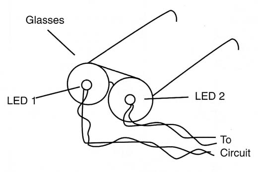
Of course, when experimenting with people, be sure to have an adult present since injuries can occur.
Also, people with certain health concerns, such as epilepsy, should not take part in these experiments.
Testing and Using
Testing is very simple. Place the batteries into the holder and turn on the S1 switch. The LEDs should alternately blink. Act on P1 to change the frequency.
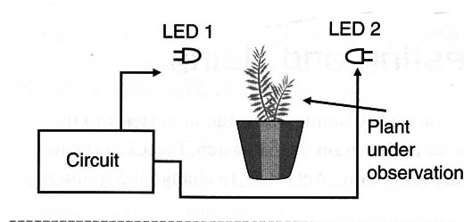
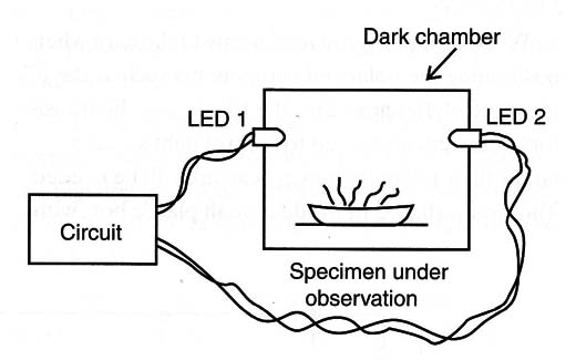
When everything is ready, place the LEDs around the plant at a distance specified by the experiment and be sure to avoid external light sources. Figure 6 shows how to set up the experiment.
IC-1: 555 integrated circuit timer
Q1: BD135 medium-power NPN silicon transistor
Q2: BD136 medium-power PNP silicon transistor
D1: 1N4148 general-purpose silicon diodes
LED1, LED2: Common high-power LEDs (see text)
R1: 4,7 k ohm,x 1/8 W resistor, yellow, violet, red
R2: 2.2 k ohm x 1/8 W resistor, red, red, red
R3, R4:1 k ohm x 1/8 W resistors, brown, black, red
R5, R6: 220 ohm x 1/8 W resistors, red, red, brown
P1: 1 M ohm linear or log potentiometer
C1: 1 µF x 12 V electrolytic capacitor
C2: 100 µF x 12 V electrolytic capacitor
B1: A 6 V source or four AA cells and holder
B1: On/off switch
Other: PCB, plastic box, wires, solder, etc.


